
Introduction
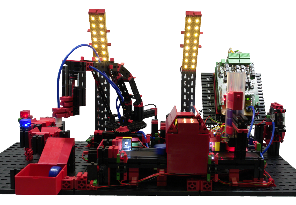
For this project a model of a simple factory has been build with Fischertechnik parts. The intention is to run industrial control simulations and show how to implement specific tasks with Ethernut and Nut/OS.
Model Overview
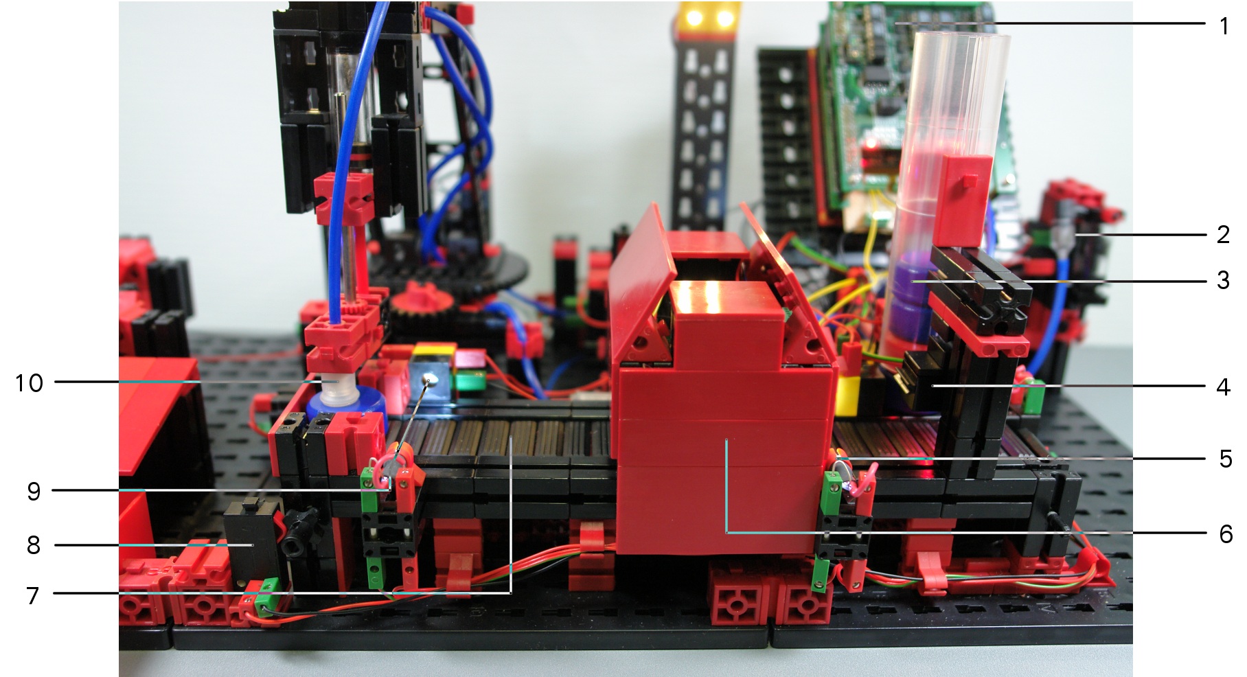
Controller (1)
The complete factory model is controlled by an Ethernut 2.1 Rev-C board with 2 CMI8848 I/O boards mounted on top.
Compressor (2)
The compressor supplies pressed air for the stack magazine (3) and the picker arm of the robot (10). It is driven by a motor and fills a pressure vessel. A pressure sensor is available to measure the pressure in the connected air tank.
The pressed air is also used to drive a pneumatic cylinder with a mechanically connected second cylinder to create a vacuum.
Stack Magazine (3)
A light barrier at the bottom of the magazine detects, if a workpiece is available. A pneumatic cylinder can be activated to shove the workpiece onto the conveyor belt (7). A color sensor (4) determines the color of the workpiece.
Conveyor Belt (7)
The conveyor belt is used to move workpieces from the stack magazine (3) to the robot (10), passing a temperature chamber (6). The belt is equipped with 2 light barriers, one at the entry of the chamber and the other at the entry of the pickup position. A pulse generator (8) generates pulses when the belt moves.
Temperature Chamber (6)
Red workpieces are heated up in the temperature chamber. Blue workpieces should not be heated up and the chamber must be cooled down first.
The chamber is equipped with large resistors to raise the temperature and 2 fans to lower it. The chamber temperature is measured by 2 temperature sensors.
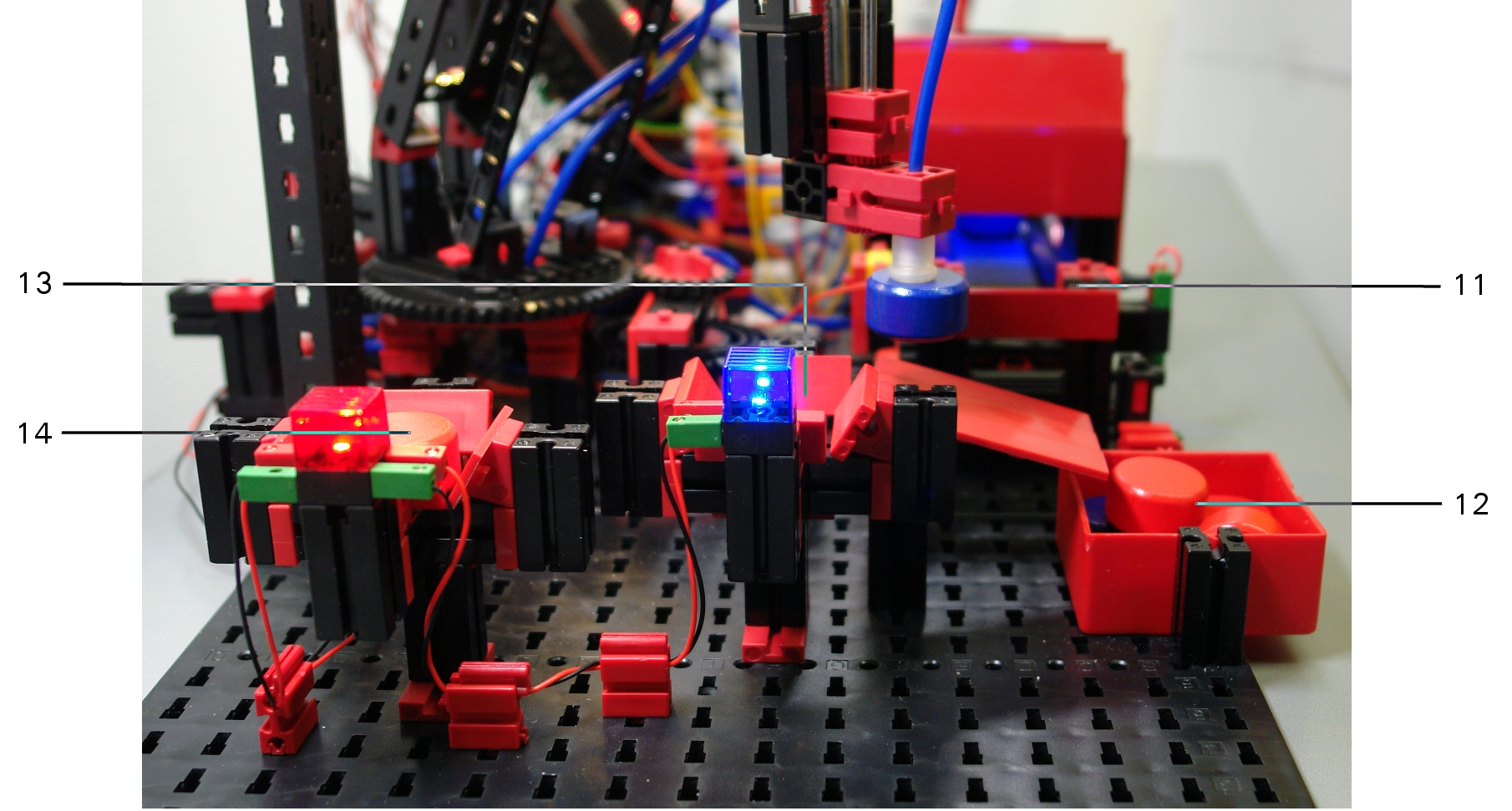
Robot Arm (10)
A spherical robot is used to pick up workpieces from the conveyor belt (7) or from a blue (13) and a red (14) deposit station. After picking up a workpiece, it will be moved by the robot to three different destinations, to the blue (13) or red (14) deposit station or to a container (12). Moving workpieces to the conveyor belt would be possible, but makes no sense. The robot arm is not able to pick up workpieces from the container.
The robot arm is equipped with 2 position sensors, a left position limit switch to determine its home position and a reed contact to determine the position of the four locations where workpieces can be picked up or deposited. A magnet is located at each position, which activates the reed contact at the robot arm when it passes the magnet.
To pick up a workpiece, the robot arm uses a pneumatic cylinder to move down a suction cup, which is connected to the vacuum pump.
Workpiece Flow
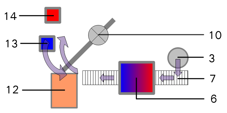
- A workpiece is shoved out of the stack magazine (3) onto the conveyor belt (7).
- A color sensor determines, if the workpiece is red or blue.
- The conveyor belt (7) immediately moves red workpiece to the temperature chamber (6).
- In the chamber (6) red parts are heated up. Blue workpieces will not enter the chamber until its temperature has been lowered.
- The conveyor belt moves the workpiece from the chamber to the robot arm (10).
- The robot arm (10) moves the workpiece to the blue (13) or red (14) deposit for inspection.
- When the next workpiece arrives at the chamber (6), the robot arm moves the workpiece from the deposit station to the container (12).
Controller Hardware
Two CMI8848 isolated I/O boards are mounted on top of an Ethernut 2 board.
Each I/O board provides up to 4 galvanic isolated digital inputs or outputs at a pluggable spring-cage terminal block. Two I/O terminal blocks are available on each I/O board. Thus, the 2 I/O boards provide up to 16 digital channels.
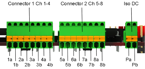
The isolated DC power connector on the CMI8848 boards is not used.
The first CMI8848 board is mounted directly to the Ethernut's expansion port. It has all standard parts mounted.
| Channel | Direction |
Ethernut Port |
Connected to | Active Status |
|---|---|---|---|---|
| 1 | Input | PE2 | Photoelectric sensor | High, when an object interrupts the light barrier at the chamber entry. |
| 2 | Input | PE6 | Reed contact | Low, when the robot arm reaches a location to pick up or drop a workpiece. |
| 3 | Input | PE7 | Contact switch | Low, when the suction cup at the robot arm fails to pick up a workpiece. |
| 4 | Output | PB7 | Fans in Chamber | Closed to lower the chamber temperature. |
| 5 | Input | PD4 | Contact switch | Continuously changes state while the conveyor belt moves. |
| 6 | Input | PD5 | Photoelectric sensor | High, when an object is available in the stack magazine. |
| 7 | Input | PD6 | Contact switch | Low, when the robot arm reaches location zero, pass the red deposit station. |
| 8 | Output | PD7 | Power resistors | Closed to raise the chamber temperature. |
The second CMI8848 board is mounted on top of the first. It has alternative parts mounted, in order to make use of different Ethernut ports.
| Channel | Direction |
Ethernut Port |
Connected to | Active Status |
|---|---|---|---|---|
| 1 | Output | PE3 | Electromagnetic valve | Closed to activate the vacuum cylinder. |
| 2 | Output | PE4 | Electromagnetic valve | Closed to move a workpiece from the stack magazine to the conveyor belt. |
| 3 | Output | PB5 | Electromagnetic valve | Closed to move down the suction cap on the robot arm. |
| 4 | Input | PB6 | Photoelectric sensor | High, when an object interrupts the light barrier near the end of the conveyor belt. |
| 5 | Output | PD2 | Electric motor | Closed to run the conveyor belt. |
| 6 | Output | PD3 | Electric motor | Closed to run the compressor. |
| 7 | Output | PD0 | Electric motor | Closed to turn the spherical robot arm. |
| 8 | Output | PD1 | Relay | Specifies the direction the robot arm is turned. The arm moves towards its home position when closed. |
Four analog signals are measured at Ethernut's analog connector.
| Channel |
Ethernut Port |
Connected to | Measured value |
|---|---|---|---|
| 1 | PF0/ADC0 | Pressure sensor | Air pressure |
| 2 | PF1/ADC1 | Photoelectric sensor | Reflection of the workpiece when illuminated by a red LED |
| 3 | PF2/ADC2 | Temperature sensor 1 | Chamber temperature near entry |
| 4 | PF3/ADC3 | Temperature sensor 2 | Chamber temperature near exit |
Controller Firmware
The software for the Ethernut board is written in C, using Nut/OS 4.9.10 for the underlying operating system.
Web Interface
A web server provides the user interface. It has been implemented with Ajax. When the browser establishes a connection, a JavaScript file is transfered, which in turn requests an SVG file. This vector file is then manipulated by JavaScript according to the data that is delivered by the web server in JSON format.
Note, that the demo animation given below is not well synchronized, which results in choppy movements. The original display is quite smooth.
Grey workpieces represent unknown and possibly unavailable workpieces. When the system is started, it is unknown whether a workpiece is available on the conveyor belt or in the red and blue deposits of the inspection area. During initialization, all sensors are calibrated and the conveyor belt is activated to move any leftover to the robot.
After successful initialization, the robot checks, if a part is available on the belt and in this case will move it to the container. If no workpiece is available in the magazine, the system stops all activities. Note the yellow signal light at the magazine.
As soon as the magazine is filled with new workpieces, the first one will be shoved from the magazine on to the belt, where a sensor checks its color. The color sensor hasn't been calibrated yet and this first workpiece and all following pieces with the same color will be moved to the container as well.
As soon as a significant difference has been detected by the color sensor, red pieces will be moved to chamber to heat them up. Blue workpieces will not enter the chamber until its temperature had been lowered to a certain limit. In the meantime the robot will check, if any workpiece is left in the red or blue deposit and move it to the container to make room for the part currently on the conveyor belt.
When a red workpiece has been sufficiently heated up or a blue workpiece passed the cooled down chamber, it will arrive at the robot arm and moved to the red or blue deposit in the inspection area. During this time a new workpiece is shoved on to the belt and the cycle repeats until no more pieces are available in the magazine.
Bill of Material
| 1 | Ethernut 2.1 Rev-C |
|
| 2 | CMI8848 1.0 Rev-B |

|
| 1 | Fischertechnik ROBO PneuVac |

|
| 1 | Fischertechnik Creative Box 1000 |
|
| 1 | Fischertechnik ROBO Conveyor Belt |
|
| 1 | Fischertechnik Relay (2-way contact) |
|