
Ethernut RS-232 Primer
This practical guide should help to connect your PC to the RS-232 interface of your embedded system.
Unfortunately, in many modern PCs the RS-232 ports had been omitted. In this case a USB to RS-232 bridge can be used.
General information about the RS-232 interface is available at Wikipedia.
Hardware
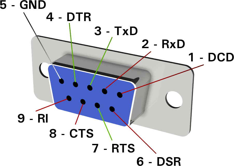
The RS-232 standard specifies 20 different singal lines. However, many of them are rarely implemented and only two signal wires plus a common ground wire are required as a minimum. While many different connectors had been in use during the last decades, the DB-9 connector had become the commonly used standard in recent years.
Due to the asymmetrical specification of the interface, there are two different connector layouts, DTE (data terminal equipment, originally used by teletype writers) and DCE (data communication equipment, originally used by modems). Usually a male connector is available on the DTE device, while a female connector is provided at the DCE.
 |
 |
|
RS-232 DB-9 male connector at the data terminal equipment (DTE). |
RS-232 DB-9 female connector at the data communication equipment (DCE). |
| Red lines are used for outputs, green lines denote inputs. | |
The signal names refer to the DTE device.
| Pin | Signal | Direction | Description |
|---|---|---|---|
| 1 | DCD | DTE <- DCE | Data Carrier Detect (when connected). |
| 2 | RxD | DTE <- DCE | Received Data (sent from DCE). |
| 3 | TxD | DTE -> DCE | Transmitted Data (sent from DTE). |
| 4 | DTR | DTE -> DCE | Data Terminal Ready (for connection). |
| 5 | GND | Common ground. | |
| 6 | DSR | DTE <- DCE | Data Set Ready (to connect). |
| 7 | RTS | DTE -> DCE | Request To Send (or DTE ready to receive). |
| 8 | CTS | DTE <- DCE | Clear To Send (or DCE ready to receive). |
| 9 | RI | DTE <- DCE | Ring Indicator (with incoming call). |
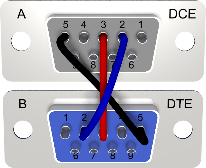
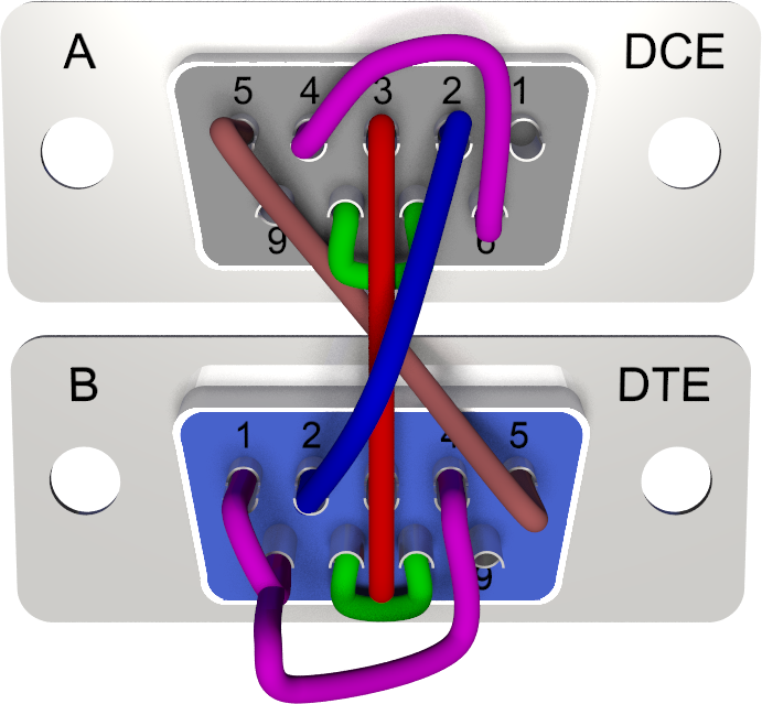
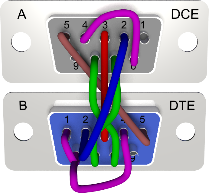
We will now look to the wiring options and present a number of often used cables. All wiring schematics are viewed from the solder side of the plugs.
Note the asymmetry between connectors at the devices and the related cable plug: The blue plugs are female types, to be plugged into the male connector of DTE devices. For the male plugs on the DCE side the grey color is used.
Straight Cables
Straight cables are used to connect a DTE with a DCE device, like attaching Ethernut 1 or 2 to a PC. They have one male plug to connect the DCE and a female plug for the DTE side.
The most simple cable requires 3 wires only.
| 3-wire straight cable | |
|---|---|
|
|
The simple 3-wire cable may not work if one end doesn't provide hardware handshake, while hardware handshake can't be disabled on the other side. In such cases a cable with shortened handshake signals will help.
| 3-wire straight cable with handshake shorts | |
|---|---|
|
|
If you are experiencing character loss, some flow control is required. For basic RTS/CTS flow control we need a 5-wire cable. Often the software will not allow to enable individual handshake signals. So we must locally provide the remaining handshakes.
| 5-wire straight cable with flow control | |
|---|---|
|
|
For full modem handshake we need a 9-wire cable. This standard straight cable may be used, for example, to attach a modem to Ethernut 3.
| 9-wire straight cable with full modem handshake | |
|---|---|
|
|
This layout is also usefull as a general extension cable.
Cross Cables
Cross cables are used to connected two DTE devices. In exceptional cases such cables can be used to connect two DCE devices, provided that the female plugs are replaced by male types.
Like with straight cables, the most simple one requires 3 wires only.
| 3-wire cross cable | |
|---|---|

|
|
If one end doesn't provide hardware handshake, while hardware handshake can't be disabled on the other side, then we need a cable with shortened handshake signals.
| 3-wire cross cable with handshake shorts | |
|---|---|
|
|
A 5-wire cable is required for basic RTS/CTS flow control. Again, it is a good idea to locally add wires to the unused handshake signals.
| 5-wire cross cable with flow control | |
|---|---|

|
|
The so called Null Modem Cable uses 7 wires and can be generally used for connecting two DTE devices.
| 7-wire cross cable with full handshake | |
|---|---|
|
|
Splitter Cables
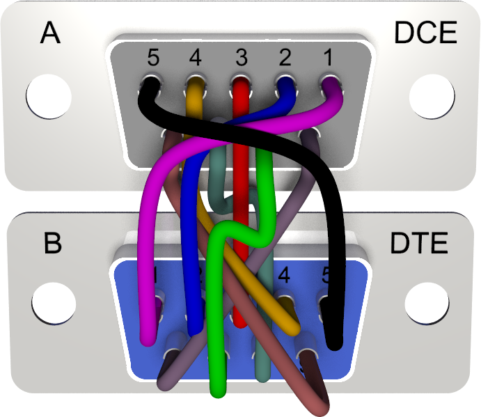
Sometimes the RTS/CTS lines are not needed and can be alternatively routed to a second serial port. This option is available on Ethernut 1, if R32 and R33 (both 0Ω) are mounted
and also on Ethernut 2 when setting the right jumpers on JP1.
Here is the wiring of a cable, which allows to connect two DTE devices to the DCE connector of Ethernut 1 or Ethernut 2.
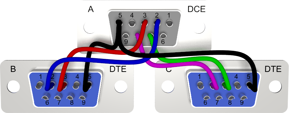
|
|
The same is available for Ethernut 3, where the serial port routing is done in the CPLD. This even allows to have RTS/CTS flow control available on one of the plugs. The cable shown below additionally provides local handshake shortcuts for the attached DCE devices.
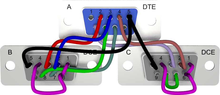
|
|
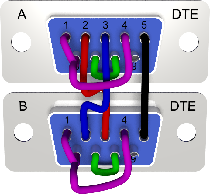
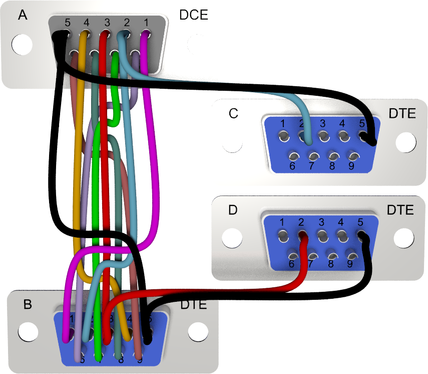
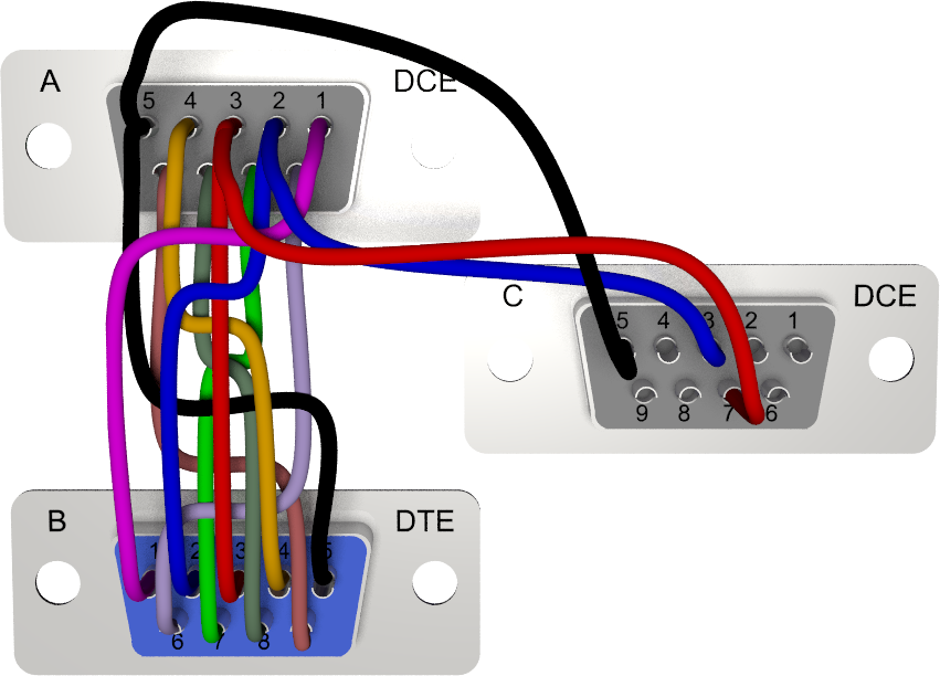
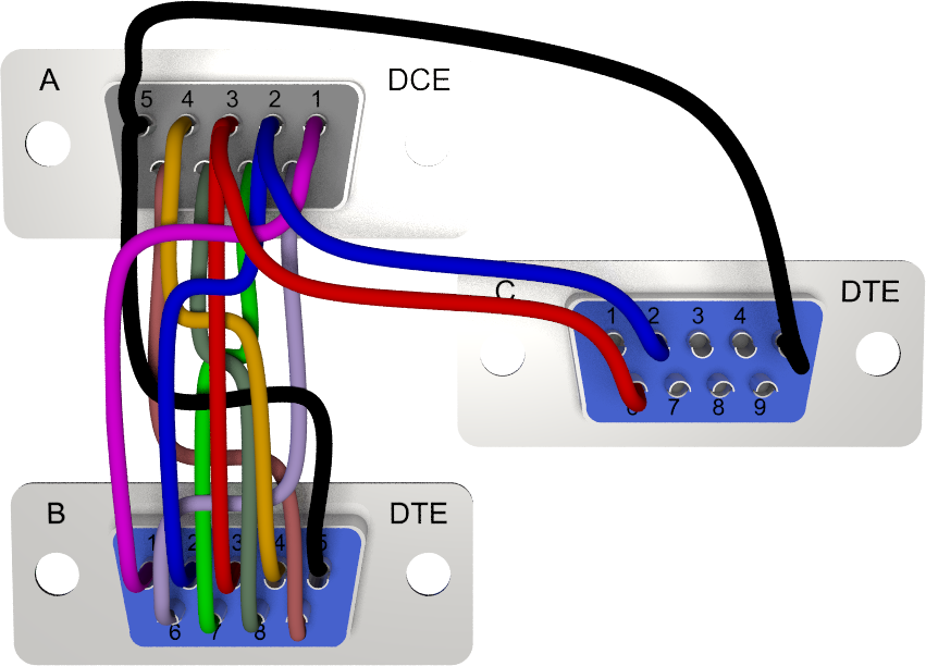
Sniffer Cables
A group of special cables are so called sniffer or monitoring cables. They are used to monitor the communication between two nodes by a third device. For full duplex operation, the monitoring device must provide two serial ports. Here is an example of a cable, which allows to monitor the traffic between a DTE and a DCE device.
|
|
As explained in the last chapter about splitter cables, Ethernut 1 and 2 boards allow to reconfigure RTS/CTS lines as secondary RxD/TxD lines. The following sniffer cable makes use of this feature.
|
|
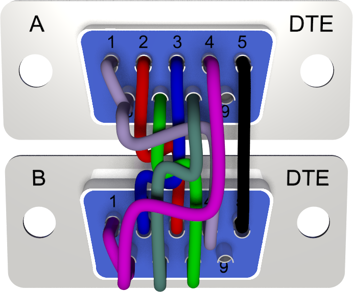
A sniffer cable for Ethernut 3 will have the following layout.
|
|
Software
Typically, RS-232 ports can be used like normal files. They can be open or closed and you can read data from and write data to previously opened ports under program control.
A basic software is the so called terminal emulator. It will send characters you type on the keyboard to the RS-232 port and display characters on the screen, which are received from the RS-232 port. Furthermore, as its name suggests, it emulates one or more computer terminals. This means, that it interprets special control characters and performs the related actions, like clearing the screen, scrolling in a specific direction, changing the character font etc. The VT52 control codes are quite popular with tiny embedded systems, because they are simple to implement and consume less memory than other more advanced emulations.
Last not least a terminal emulator provides menus or command line options to configure the RS-232 interface parameters, like:
-
Baudrate
A maximum of 115,200 Baud is supported by most desktop PCs, while embedded systems often allow much higher rates. For debug output, most Nut/OS applications use 115,200 Baud by default. -
Number of data and stop bits
While there is always 1 start bit only, there may be 1 or 2 stop bits. Even 1.5 stop bits are possibly. Either 5, 6, 7 or 8 bits may be used for the data. In order to support the full 8-bit character set at minimum overhead, most applications use 8 data bits and 1 stop bit. -
Parity
This bit adds safety at the cost of additional overhead. Typically no parity bit is transmitted. -
Handshake
Todays embedded systems and PCs are fast enough to transfer data at 115,200 Baud or higher rates without losing characters. Thus, hardware and software handshake can be switched off in most cases.
While some terminal emulators are running in the GUI (graphical user interface) others are simple command line applications, which need to be started in a so called DOS-Box or command line shell, whatever it is called with your operating system. The OS X command line window is called Terminal, which is a bit confusing in this context.
Windows
RS-232 ports are named com1, com2, com3 and so on. Available terminal emulators are, among many others:
-
HyperTerminal
Included in earlier Windows releases, but no longer available in Windows Vista.Pros:
-
Easy to access if installed with your Windows release.
-
Supports all COM ports.
-
Good terminal emulation, including VT52.
Cons:
-
At least those versions we used are most unreliable and buggy. If anything doesn't work, blame this program first before wasting time looking somewhere else.
-
Doesn't support raw transfer without terminal emulation.
-
-
Pros:
-
Easy configuration.
-
Reliable connections.
-
Free software with source code.
Cons:
-
Window contents is cleared when resized.
-
Supports COM1 to COM4 only.
-
Doesn't support VT52.
-
Doesn't support raw transfer without terminal emulation.
-
Linux
On Linux the serial port devices are named /dev/ttyS0, /dev/ttyS1 and so on. When using a USB to RS-232 bridge, it may be /dev/usb/ttyUSB0 resp. /dev/usb/ttyUSB1 instead.
A simple terminal emulator is:
Others are available as well.
Unix
Serial port devices may be named /dev/ttyC0, /dev/ttyC1 etc. Check your /dev directory.
The tip utility runs on the command line and is available on many UNIX systems. The following command starts tip for the first serial port at 115,200 Baud.
$ tip -115200 /dev/ttyC0
Mac OS X
Except some old machines, Macs do not have serial ports. Thus, a USB to RS-232 bridge is always required. Fortunately they are cheap, but before buying one, make sure that OS X drivers are available.
In most cases the first devices is named /dev/tty.usbserial0, the second is /dev/tty.usbserial1 and so on.
The screen utility is included in OS X and you can run it by entering the following command in a Terminal window:
$ screen /dev/tty.usbserial0 115200
Other terminal emulator are: