
Using RS485 With Ethernut 2
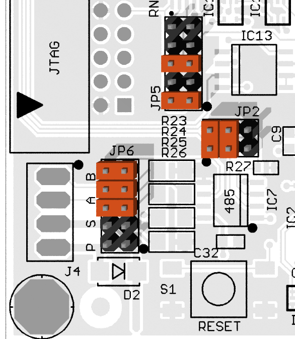
Jumper Settings
JP1 1-2
Connects UART0 transmit to RS232 transmit.
JP1 3-4
Connects UART1 transmit to RS485 transmit.
JP1 9-10
Connects UART1 receive to RS485 receive.
JP1 11-12
Connects UART0 receive to RS232 receive.

JP2 1-2
Connects PORTD Pin 5 to negated RS485 receive enable. Thus, driving PD5
low will enable the receiver.
JP2 3-4
Connects negated RS485 receive enable to RS485 transmit enable. This
way the RS485 transmitter will be enabled when the receiver is disabled
and vice versa.
JP6 5-6
Enables the RS485 termination. This jumper should be set on the first
and the last node of the RS485 bus.
JP6 7-8
Enables a pull-down resistor on RS485 line A. Should be set at one node only.
JP6 9-10
Enables a pull-up resistor on RS485 line B. Should be set at one node only.
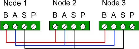
Cabling
RS485 requires two wires A and B only and may use an optional shield S.
System Software
Start the Nut/OS Configurator, load ethernut21b.conf and modify the UART1 driver settings as shown in the screenshot below.
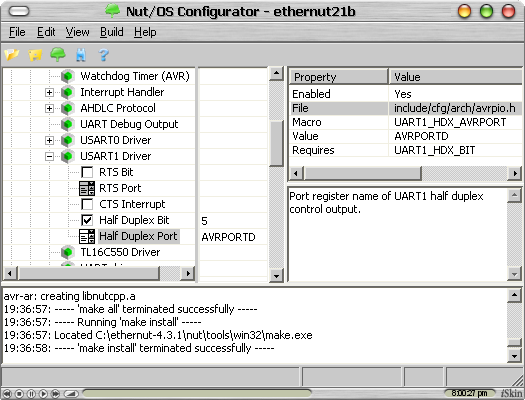
When done, rebuild Nut/OS.
Application Software
test485.zip
Contains two sample test application for two Ethernut Boards 2.1. One is an RS485 master,
which sends out a text line and listens for any response. The other one is a slave, which
listens for text lines and echoes them back.
These application demontrate text mode transfer, where end of line characters are automatically converted. Up to and including Nut/OS Version 4.2.1 (and Beta 4.3.1) there are two bugs, which will let the transfer fail.
Nut/OS requires to register any device that will be used by the application. For best portability it is recommended to use the macros provided by the header file board.h.
#include <dev/board.h>
...
NutRegisterDevice(&DEV_UART1, 0, 0);
After having registered the device, several UART specific options need to be set by calling the _ioctl() function. We will set half duplex mode first.
#include <io.h>

u_long flow_485 = USART_MF_HALFDUPLEX;
...
_ioctl(_fileno(rs485), UART_SETFLOWCONTROL, &flow_485);
In order to avoid a floating UART receive input when the RS485 receiver output is disabled, we must enable the pull-up on that line.
sbi(PORTD, 2);
Anyway, we can now use normal stdio functions to open or close the device as well as reading data from or writing data to the device.
#include <stdio.h>

FILE *rs485;
char buffer[16];
...
rs485 = fopen(DEV_UART1_NAME, "r+");
fprintf(rs485, "Hello world!\n");
fflush(rs485);
fgets(buffer, sizeof(buffer), rs485);
...
Collision Detection
Moving the jumper at JP2 3-4 to position JP2 5-6 will put the receiver under control of PORTD Bit 4. Configuring this port bit for output and setting it to low will permanently enable the receiver.
Each character sent will then be received immediately. If another node enables its transmitter at the same time, the characters will be scrambled. This way we are able to detect transmit collisions.
Pitfalls
There are many <grien>. Here's one:
When calling fgets() in text mode (cooked, not binary), the function will return as soon as the carriage return arrives. At that time the linefeed character is still on the line and some delay is required before a new transmit is allowed. The actual delay time must be based on the baudrate, e.g. about 10 ms at 1200 Baud.
Good Luck!