
Medianut 2
All Ethernut boards provide a 64-pin expansion port, which had been implemented on the ATmega128 based boards first. For later ARM based boards special care had been taken to offer similar peripherals at the same pins. This allows to design add-on boards, which can be used with all Ethernuts.
Medianut 2 is a small MP3 decoder add-on board for Ethernut. After the VS1001K decoder chip used on its predecessor Medianut 1 became obsolete, a new enhanced version 2 had been designed.
Features
- Supports VS1011 and other decoder chips from VLSI Finland.
- Compatible with 5V and 3V Ethernut Boards.
- On-board ATmega168 unburdens the Ethernut CPU of I/O scanning.
- Advanced LCD Interface can be used as 4 or 8 bit parallel and serial connections.
- On-board switching power supply.
Medianuts equipped with the VS1011E are available at your local Ethernut Distributor or can be ordered directly from www.egnite.de.
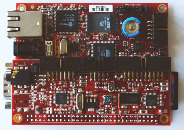
Medianut 2 mounted on Ethernut 3
Hardware Documentation
Schematic Sheet 1
MP3 Decoder and audio connectors.
Schematic Sheet 2
CPU, LCD interface and Ethernut extension connector.
Schematic Sheet 3
Power supply.
Medianut 2 Connectors
Lists all signals.
medianut20d.zip
Eagle CAD Files of Medianut 2.0 Rev-D. You can use this as a start point for
creating your own hardware. The original design may look a bit overdone for
your purpose and could be easily minimized.
| Part | Function |
|---|---|
| 74LVC244 | Used for voltage level translation. It is not required if your host board is 3.3V logic only. However, you also need run the ATmega168 MCU with 3V. Also take care of SPI bus sharing. |
| ATmega168 | Required for LCD and keyboard only. Both may be controlled directly by the Ethernut Board. |
| LT1616 | This switching regulator can be avoided, if you feed the Medianut from the Ethernut's regulated power supply. |
Known Hardware Problems
The buffer enable signal for the audio codec lines had been tied to the audio codec chip select. This forbids to run the audio codec in all chip select modes. To fix this, the buffer enable must be tied to a dedicated GPIO pin.
If you ordered a readily built Medianut 2 board, you will notice a tiny red wire:
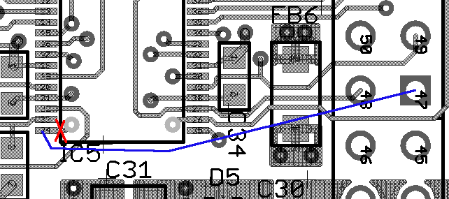
Here's the related change in the schematics:

Software Support
Support for Medianut 2 is available since Nut/OS beta release 4.3.2. This early library module consists of vs10xx.c and an associated header file vs10xx.h and is compatible with the initial module vs1001k.c for Medianut 1. This code is not really state-of-the-art, but allows to run existing applications for the older Medianut 1 with the newer board.
While that old interface is still available, Nut/OS 4.8 introduced a new SPI bus driver model. Only the SPI controller hardware is handled in a single, target specific bus controller driver. All drivers for SPI devices, like the VLSI codecs, can be implemented in target independent driver and therefore are instantly available on all targets, which provide an SPI bus controller driver.
The new spi_vscodec module makes use of this new SPI driver model. Therefore, VLSI codecs are automatically supported for all platforms with SPI bus drivers.
Nut/OS Configuration
The Nut/OS distribution contains ready to use configurations for all officially supported boards, including Ethernut 1, 2, 3 and 5, for which the Medianut add-on had been designed. Nut/OS configuration and building is explained in detail in the Ethernut Software Manual. The following chapters will explain the Medianut 2 specific settings only. Our configurations had been tested with Nut/OS version 4.10.3.
Medianut 2 contains two SPI devices: An audio codec and an ATmega168. The latter is used to handle an optional LCD and keyboard interface. Due to a design flaw in the SPI bus driver, a logical chip select number must be provided by the application code when registering an SPI device. To make applications running on all targets without source code modification, we will use the same logical chip selects on all Ethernuts. To avoid conflicts with existing applications, which often use chip select 0 for an on-board serial flash device, we will generally use chip select 1 for the codec and chip select 2 to access the LCD/keyboard interface. However, you are free to configure other chip selects. Until now, all Nut/OS SPI drivers use simple GPIO functions to control the chip selects. Chip selects provided by the peripheral functions of the CPU are not used. Therefore, any available GPIO pin may be configured as a chip select.
Configuration for Ethernut 1.3
This board doesn't have any on-board SPI devices. The SPI bus hardware of the ATmega128 CPU is exclusively used by the Medianut add-on board.
| CS | SPI Device | Port |
|---|---|---|
| 0 | Not used | |
| 1 | Medianut 2 audio codec | PB0 |
| 2 | Medianut 2 ATmega168 MCU | PD7 |
Configuration for Ethernut 2.1
On this board the SPI bus hardware of the ATmega128 CPU is attached to an on-board DataFlash, which is typically configured for logical chip select 0.
| CS | SPI Device | Port |
|---|---|---|
| 0 | Ethernut 2 Serial Dataflash | PB4 |
| 1 | Medianut 2 audio codec | PB0 |
| 2 | Medianut 2 ATmega168 MCU | PD7 |
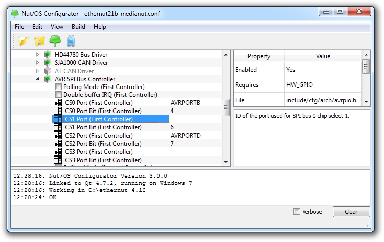
Furthermore, PB4 and PD4 will be used to reset the MP3 decoder and the Medianut
MCU resp. The following screen shot shows the required SPI configuration for
Ethernut 2. You will find the settings in the Configurator's component tree
below
Architecture -> AVR -> Polled SPI.
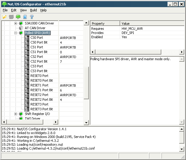
The same configuration will work with Ethernut 1, though chips select 0 is not used because this board has no Dataflash Memory.
Configuration for Ethernut 3.1
Ethernut 3 doesn't provide a hardware SPI. We could have implemented one in the CPLD, but the ARM7 CPU is probably fast enough for doing software SPI, also known as bit banging. We will configure the chip selects for the first two devices of SPI 0.
| CS | Ethernut 3 SBBI0 Device | Port |
|---|---|---|
| 0 | Medianut 2 VS1011E MP3 Decoder | P0 |
| 1 | Medianut 2 ATmega168 MCU | P18 |
| 2 | Not used | |
| 3 | Not used |
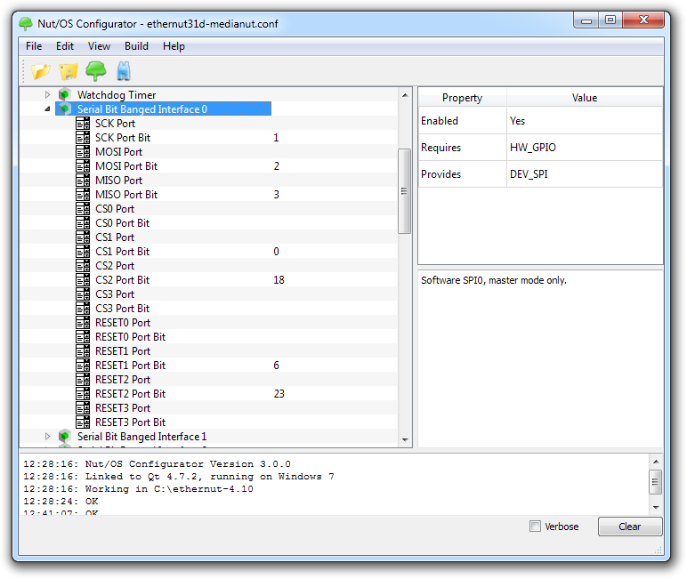
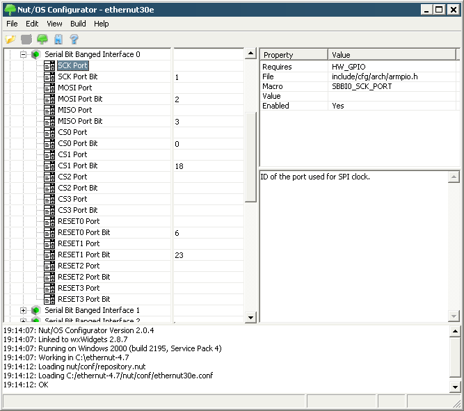
For resetting the decoder and the ATmega168 we choose port bits P6 and P23
resp. Last not least, P1 (SCK), P2 (MOSI) and P3 (MISO) are used for the SPI
implementation. The related settings in the Configurator's component tree are
below
Device Drivers -> Serial Bit Banged Interface 0.

In Nut/OS 4.7 and later this looks more tidy.
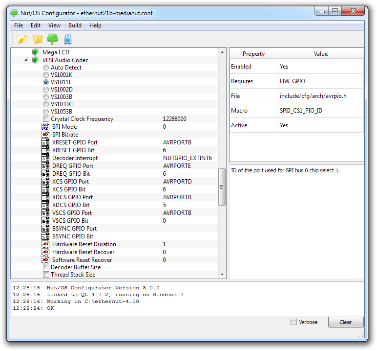
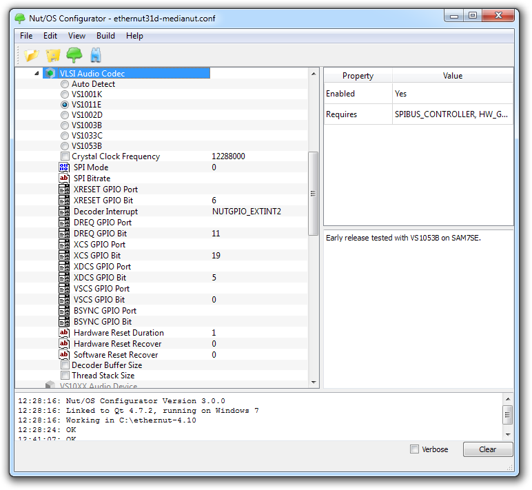
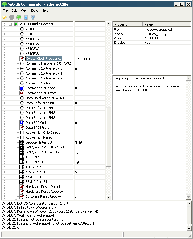
After having done the general SPI configuration, we are ready to specify the
decoder settings. They are available below
Device Drivers -> VS10XX Audio Decoder.
The following screen shot shows the configuration for Ethernut 2.

The configuration for Ethernut 3 is only slightly different.

Here's a screenshot from Nut/OS 4.7.
We are almost done with the configuration. The last part is the interface to the ATmega168. Actually, everything had been specified already during SPI configuration. However, the Ethernut Board will also be able to upload the firmware into the ATmega168 program memory by using the AvrTarget API (which is new in Nut/OS 4.3.2). This module is not quite smart yet. For example, we need to specify the target's Flash Page Size.
The related settings are the same for all Ethernut Boards and can be found
below
Device Drivers -> AVR Serial Programming.
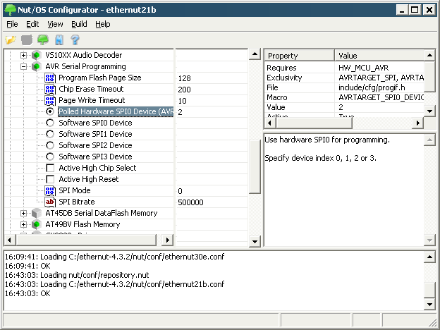
If most items are grayed out, you need to edit conf/dev/dev.nut near line 1960. Remove the line containing
requires = { "HW_MCU_AVR" },
below the macro definition
macro = "AVRTARGET_SPI0_DEVICE",
After properly configuring all parts, build the Nut/OS libraries and create an application tree as described in the Ethernut Software Manual.
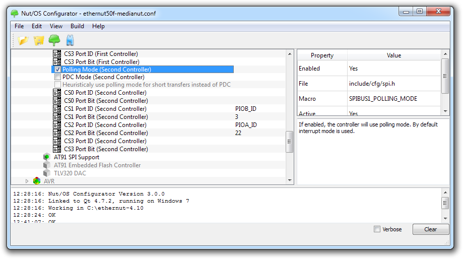
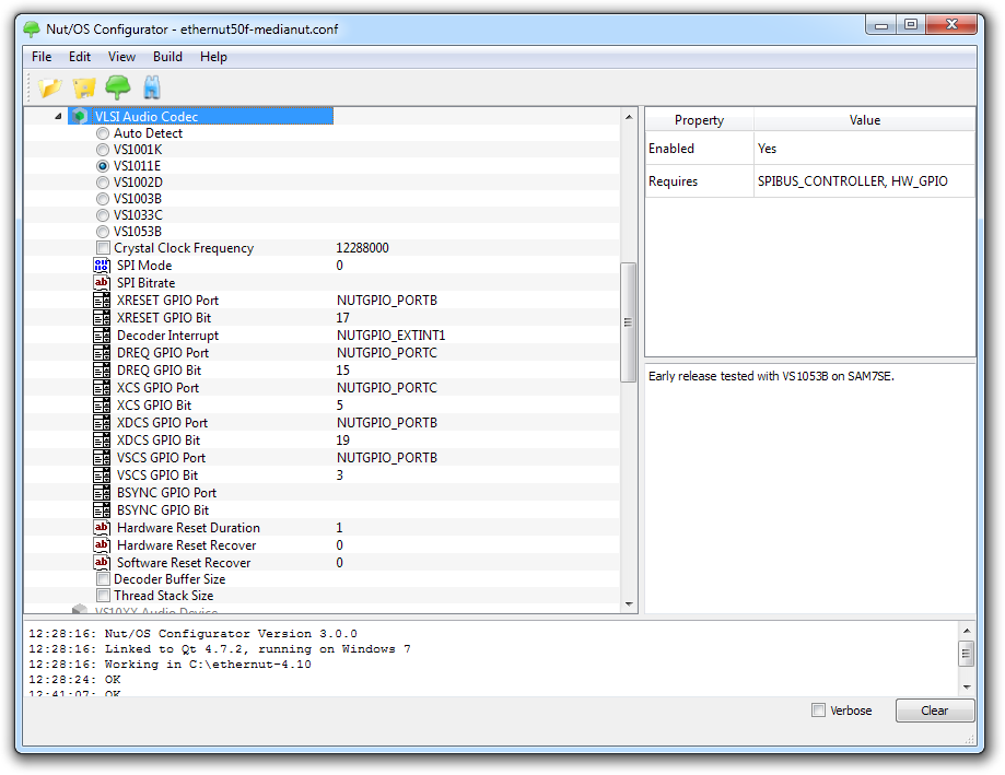
Configuration for Ethernut 5.0
Creating an MP3 Application
For many developers the most interesting project will be the Internet Radio. This link is a bit outdated, but should work with our new Medianut as well. Just two important changes must be considered.
-
The MCU on Medianut 2 needs to be loaded with the proper firmware in order to get an LCD or keyboard running.
-
Due to its compatibility with the vs1001k module, the new vs10xx driver can't coexist in the same library. You need to add a copy of nut/dev/vs10xx.c in your application directory and add this file to your application's Makefile.
More...
I'm aware, that this page leaves you in the dark, if you are a complete newbie. We will add more information soon. In the meantime you may try one of the ready-to-use samples. Copy them to the application directory which you created with the Nut/OS Configurator.
enut21b-media2vs10xx.zip
Plays three simple MP3 files located in the UROM file system. Also contains the
Medianut 2 MCU firmware and all required routines to burn it into the device.
The binaries for Ethernut 2 are included. For Ethernut 1 you can create them
with make clean followed by make install or make burn.
enut30e-media2vs10xx.zip
Like enut21b-media2vs10xx.zip, but pre-build for Ethernut 3.
enut30e-musicbox.zip
Plays all MP3 files found in the root directory of the MultiMedia or SD Card
inserted into the Ethernut 3 card socket.