SISP AVR Programming Adapter
The SISP programming adapter is a DIY project from early 2003. Today many low cost adapters are available, which use modern hardware, provide more feature and support more target CPUs. The following description may be still of academic interest.
An general overview about in-system programming is available on this page.
Introduction
This article presents some information about how to upload your software into the Ethernut or any other AVR microcontroller board. A not-so-simple programming adapter is presented, which enables you to program the target board by using the RS232 interface (aka. COM port) of your PC.
Note, that the hardware of this adapter should work for almost any AVR target with ISP interface, but the software is quite limited. It has been tested with ATmega103 and ATmega128 chips only. While programming flash memory, fuses and lock bits of these MCUs works fine, the current version also fails programming the on-chip EEPROM.
Another word of caution. Playing around with the software inside your programming adapter or with the ATmega fuse settings is risky, as long as you don't take special care. Always make sure, that you got a second programming alternative or an Ethernut board with a working bootloader, if you change the adapter software. Also take care not to disable the ATmega oscillator, when reprogramming the fuse registers.
Serial And Parallel Programming
There are several methods to upload your software to a target device like an Ethernut Board. One of the most advanced is using an Ethernet bootloader based on the DHCP, BOOTP and TFTP protocols. But how to get the bootloader software into the target system? This requires a special hardware called programming adapter, also known as programming dongle.
Programming AVR devices like the ATmega128 is fairly simple. There is no need
for special
programming voltage supply and timing is not very strict as long as you don't
violate the
speed limit. Note however, that AVR chips typically support two programming
modes,
 parallel and serial programming. Parallel programming is very fast and
excellent for
volume production, but it requires an additional 12 Volts supply and is most
often done
before soldering the chip onto the PCB. The simple serial programming method is
the first
choice for low volume production and during development. Just three pins are
used in
this mode, an input line, an output line and a clock line. In addition, the
RESET line
of the chip must be held low during programming. Because serial programming is
done while
the chip is already soldered onto the target board, it is also called In-System
Programming
or ISP.
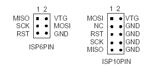
Many AVR boards are equipped with a 6 or 10-pin connecter, where you can
plug-in
the programming adapter. The 6-pin version had been used initially by Atmel,
but they
later switched to the 10-pin version which provides additional ground lines.
Ethernut
uses the 10-pin version.
parallel and serial programming. Parallel programming is very fast and
excellent for
volume production, but it requires an additional 12 Volts supply and is most
often done
before soldering the chip onto the PCB. The simple serial programming method is
the first
choice for low volume production and during development. Just three pins are
used in
this mode, an input line, an output line and a clock line. In addition, the
RESET line
of the chip must be held low during programming. Because serial programming is
done while
the chip is already soldered onto the target board, it is also called In-System
Programming
or ISP.
Many AVR boards are equipped with a 6 or 10-pin connecter, where you can
plug-in
the programming adapter. The 6-pin version had been used initially by Atmel,
but they
later switched to the 10-pin version which provides additional ground lines.
Ethernut
uses the 10-pin version.
On the ATmega128 the ISP input and output lines are shared with the transmit and receive lines of the first on-chip USART. This adds a minor problem. As long as the adapter is connected, the output line of the adapter shares the same MCU input line as the RS232 receiver output, which is included on almost any ATmega128 board. To overcome this, Atmel used an additional line called programming enable or programming LED on pin 3 of the 10-pin connector. The programming software on the PC will set this line low before starting the programming cycle. This line can be used to switch the pins on the ATmega from the RS232 driver to the ISP connector. On Ethernut 1.3 this is done by a multiplexer chip (IC7, 74HC4053) and the line will also lit the red programming LED. But not all programming adapters provide this signal, so on Ethernut 1.3 a jumper has been added to manually pull this line low. Ethernut 2.0 completely ignores this signal and also the programming LED has been eliminated. Instead, the RESET line is used to disable the RS232 driver. Remember, that RESET will be held low during programming. This solution might look perfect, but requires a more expensive RS232 driver with a disable feature.
JTAG Programming
 The first versions of the Ethernut Board were based on the ATmega103 and hasn't
changed
much since then. When Atmel later introduced the ATmega128, the ATmega103 was
replaced
without any layout modification. The new chip offers a JTAG interface, which
has to be
connected to the upper 4 bits of PORTF. JTAG is completely different from ISP.
It can
not only program the target device, but adds additional hardware and software
debugging
support. And it requires a more advanced programming adapter which costs much
more
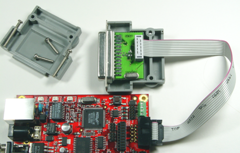
than a simple ISP adapter. Atmel's "low cost" JTAG adapter, called ATJTAGICE,
comes
with an adapter cable, which can be used to connect it to an
Ethernut 1.3 board,
which never had been designed to support JTAG. But handling this cable is very
uncomfortable.
The 10-pin connector on the Ethernut 2.0 can be switched between JTAG and ISP
mode by
a 20-pin jumper. Changing the jumper isn't convenient, but typically done once
only.
The first versions of the Ethernut Board were based on the ATmega103 and hasn't
changed
much since then. When Atmel later introduced the ATmega128, the ATmega103 was
replaced
without any layout modification. The new chip offers a JTAG interface, which
has to be
connected to the upper 4 bits of PORTF. JTAG is completely different from ISP.
It can
not only program the target device, but adds additional hardware and software
debugging
support. And it requires a more advanced programming adapter which costs much
more
than a simple ISP adapter. Atmel's "low cost" JTAG adapter, called ATJTAGICE,
comes
with an adapter cable, which can be used to connect it to an
Ethernut 1.3 board,
which never had been designed to support JTAG. But handling this cable is very
uncomfortable.
The 10-pin connector on the Ethernut 2.0 can be switched between JTAG and ISP
mode by
a 20-pin jumper. Changing the jumper isn't convenient, but typically done once
only.
Due to their high price when compared to ISP adapters, JTAG adapters are mainly used for debugging.
ISP Adapters
The often used terms "serial or parallel programming adapter" may be misleading, because some ISP adapters use the PC's parallel port while others are connected to one of the PC's serial COM ports. But both of them use the AVR's serial programming mode.
ISP adapters for the PC parallel printer port are most simple. Some of them do not even need any active components. But you can imagine, that directly connecting your Ethernut board to the PC parallel port may cause problems. Therefore, most adapters use a line driver. But still this isn't very save. The parallel port on the PC is not very well protected against shortcuts or overload and several people killed this port by plugging the adapter in or out without switching off the Ethernut power supply first. Very bad, when you did this to your notebook computer.
In opposite to the parallel port, the serial port on the PC is very well protected. But again, there are two types of programming adapters for the COM port. The simpler type uses the port lines directly to generate the programming pulses for AVR chip. The second type sends programming commands and program data to the adapter, which interprets them and accordingly generates the pulses. This adapter type needs some kind of processing capabilities, typically provided by a microcontroller build into the adapter.
For a long time Ethernut Starterkits sold by egnite came with a line driver adapter for the PC parallel port. A similar design is available at www.avr-asm-tutorial.net.
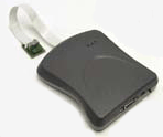
Later they were replaced by the serial port version, which uses an AT90S2313. egnite put it in the same housing, but added a yellow LED to make it visually distinguishable from the parallel port version. Michael Fischer (the guy who did the IDE interface for Ethernut) was the driving force. He modified an existing design from the Atmel application note AVR910, which is based on an AT90S1200.
But finally egnite decided to completely rewrite the software in order to make it compatible with AVR Studio. (Btw. this company did this more than once, receiving some very well working contribution, saying thank you and later publishing something completely different with a handful of new bugs, shamelessly naming the original author :-)). This adapter, named SISP, will be presented below.
As the PC industry is moving towards USB with some notebooks not even equipped with a parallel or serial port, this interface becomes more important.
ISP Software
What ever type of adapter you intend to use, you should check the available programming software too. There is no solution, that fits everywhere and a large variety of tools is available in the Internet. Luckily, almost all of them are free.
Atmel offers AVR Studio. This isn't just a simple programming software, but an integrated development environment with assember, debugger, simulator, source code editor and other goodies. It's free, but only available for the Windows operating system. Two additional command line tools for ISP are included as well, STK500.EXE and AVRPROG.EXE.
Originally written by Uros Platise, uisp is a command line tool for the Linux operating system. It's currently maintained by Ted Roth and Marek Michalkiewicz and available at savannah.nongnu.org. A port to the Windows operating system is included in the WinAVR distribution. Before Ted and Marek took over the uisp support, several programmers tried to enhance it and find it a hard nut to crack. The source code is a mixture of C and C++, handles many kinds of different hardware and is not really easy to follow.
Brian Dean started to develop AVRPROG for the BSD operating system. Later it has been renamed to AVRDUDE to avoid conflicts with Atmel's AVRPROG.EXE. At the time of this writing AVRDUDE is maintained by Brian Dean, Ted Roth and Jörg Wunsch at savannah.nongnu.org. Again, the Windows port is part of the WinAVR distribution.
The commercially supported ICCAVR compiler IDE offered by ImageCraft comes with it's own programmer GUI. However, it uses an external call to STK500.EXE to deal with STK500 compatible programmers until version 6.28. Therefore, AVR Studio had to be installed too. Since version 6.29, ICCAVR handles it internally.
Last not least, Claudio Lanconelli developed PonyProg, a powerful programming software for the Windows operating system. His company LancOS does not only offer free downloads of this software, but also low cost ISP adapters.
SISP Hardware
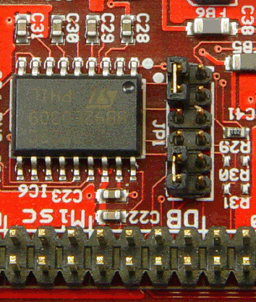
 In fact, the SISP is a tiny AVR system on its own. The schematic is available
here. It contains two chips, an AT90S2313
MCU and a MAX202 RS232 transceiver. The MCU communicates with the PC over the
RS232 port and controls the 10-pin ISP interface and the LED.
In fact, the SISP is a tiny AVR system on its own. The schematic is available
here. It contains two chips, an AT90S2313
MCU and a MAX202 RS232 transceiver. The MCU communicates with the PC over the
RS232 port and controls the 10-pin ISP interface and the LED.
There are two modifications on the version sold by egnite: First, C8 is not mounted, because it simply doesn't fit in the housing. Such things happen, when software people are designing hardware. Second, the crystal's frequency had been reduced to 3.6864 MHz.
SISP Firmware
The software of the SISP adapter has been completely written in assembler. Main reason is the very limited RAM of the AT90S2313, but also the required timing. The first versions had been developed using AVR Studio, which includes a build-in assembler. Finally the source code had been ported to the AVR-GCC assembler.
First goal was, to get it working with AVR Studio. That wasn't as easy as expected, because the software insists on using 115.200 Baud. Worse, it ignores any attempt to reduce the amount of data send within one telegram and sticks to 256 bytes. After some calculations it became obvious, that this is no big problem when programming the ATmega flash. But it would be impossible to get that amount of data into the EEPROM, because this memory type must be programmend byte by byte and is very slow. On the other hand, the 2313 MCU doesn't offer sufficient RAM to buffer a 256 byte telegram. Most applications do not require a pre-programmed EEPROM, so this wasn't a big deal really.
Version 1.0.1 worked fine with Ethernut 1.3, but seems to fail with previous Ethernut versions and misarably failed with other MCUs. Due to lack of time, nothing was changed until the release of Ethernut 2. As explained, this board doesn't use a multiplexer anymore and ignores the programming enable line. As long as the adapter is plugged in the board's ISP socket, UART0 input stops working. Another problem appeared after the release of ICCAVR version 6.29. ImageCraft decided to provide their own programming and not to call STK500.EXE any longer. Unfortunately, SISP stopped working with this new release. Something had to be done.
Version 1.1.1 mainly corrects the problem with Ethernut 2 by simply setting its output lines into high-Z mode during inactivity. Further debugging of the previous release showed, that the ISP timing has been somewhat critical, it was a bit too fast at some points. It fails to program flash memory of devices, which are running at clock speeds below 8 MHz. After correcting this, it worked with ATmega128 MCU clock speeds down to 2 MHz and also the ICCAVR problem seems to have disappeared.
The archive sisp-1.1.1.zip contains the firmware source code and the compiled hex file.
The software had been ported from AVR Studio to GCC, in order to implement a programmer update procedure for the Ethernut board, which will be explained now.
The Chicken and Egg Problem
As stated above, SISP programmer is a tiny AVR system on its own and consequently needs to be programmed. If you got a STK500, a STK200/300 dongle or a pre-programmed Ethernut board with a bootloader, this is an easy task. If you don't get any of these, then there's a new problem to be solved. Either pass the SISP programmer to a friend, who owns any of these tools and let him do the programming. Or build yourself a simple programmer for the parallel port and use this one to upload the software into the SISP.
If you got an Ethernut board with a working bootloader or any working
programming
adapter and software, initializing the SISP adapter has become quite simple.
Using a bootloader is preferred. In case you of any failure during adapter
programming, you still got the bootloader left, specially if you try to update
your
one and only ISP adapter,
Since Nut/OS 3.3.2 a new application named ISP2 (I-S-P-square) has been included for this task. Because of the assembly process involved, it is available for GCC only, but ImageCraft users can pick up the pre-build hex file from the Nut/OS bin directory.
 The GCC makefile will assemble the SISP firmware, convert it to a Nut/OS
ROM file by using the crurom utility, compile the C sources of the application
and link everything into a hex file and a raw binary image. Now you can upload
the
result to the Ethernut board by using the hex file with any programming
software or
the binary image with the Ethernut bootloader. After that has been done, the
Ethernut board will start this application and print out success or failure
messages
on UART1. Indeed, UART0 is not available, because these pins are connected to
the ISP adapter and used for the SISP programming. Owners of Ethernut 2 boards
are lucky, because they can switch the DB9 from UART0 to UART1 by changing the
jumpers at JP1. If you are using Ethernut 1.3,
you are in the dark, but the procedure will still work for you.
The GCC makefile will assemble the SISP firmware, convert it to a Nut/OS
ROM file by using the crurom utility, compile the C sources of the application
and link everything into a hex file and a raw binary image. Now you can upload
the
result to the Ethernut board by using the hex file with any programming
software or
the binary image with the Ethernut bootloader. After that has been done, the
Ethernut board will start this application and print out success or failure
messages
on UART1. Indeed, UART0 is not available, because these pins are connected to
the ISP adapter and used for the SISP programming. Owners of Ethernut 2 boards
are lucky, because they can switch the DB9 from UART0 to UART1 by changing the
jumpers at JP1. If you are using Ethernut 1.3,
you are in the dark, but the procedure will still work for you.
After switching to UART1 on Ethernut 2 at 115,200 Baud and pressing reset, a
message will
appear, that the programming failed (Version 1.3 owners may simply believe it).
This shows, that everything is fine.
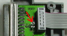 In order to enable the SISP hardware re-programming, the adapter's RESET line
must be held
low. In the
SISP schematic
you will find a jumper JP1 for this purpose. On ISP adapters being distrubuted
by egnite,
this part is not mounted, but you can carefully use a piece of wire to shortcut
the empty
pads. After having done that, reset the Ethernut board again and wait until
ISP2 displays
success. Ethernut 1.3 users may wait at least 30 seconds. Now remove the RESET
jumper shortcut
on the SISP board and watch the yellow LED blinking three times. That's it, you
are ready
to use your new adapter.
In order to enable the SISP hardware re-programming, the adapter's RESET line
must be held
low. In the
SISP schematic
you will find a jumper JP1 for this purpose. On ISP adapters being distrubuted
by egnite,
this part is not mounted, but you can carefully use a piece of wire to shortcut
the empty
pads. After having done that, reset the Ethernut board again and wait until
ISP2 displays
success. Ethernut 1.3 users may wait at least 30 seconds. Now remove the RESET
jumper shortcut
on the SISP board and watch the yellow LED blinking three times. That's it, you
are ready
to use your new adapter.
In case this procedure failed, read on.
Disaster Management
There are those bad days, where all precautions fail and you end up with nothing. If you misprogrammed the ATmega fuses, the crystal as well as the internal oscillator may stop working. In this case, not everything is lost, check the Ethernut FAQ.
If you spoiled the software on the SISP without a running bootloader, you are back to the chicken and egg problem.
One of the worst things you can do is, misprogramming the fuses and disabling the JTAG and the ISP interface. There's no other way than replacing the AVR chip in this case. You can still re-awake the spoiled one, but only through parallel programming, which is not possible on most AVR boards.
Coming Next
The unability to program the target EEPROM is caused by the small amount of RAM. Replacing the AT90S2313 by the ATmega8 will solve this.
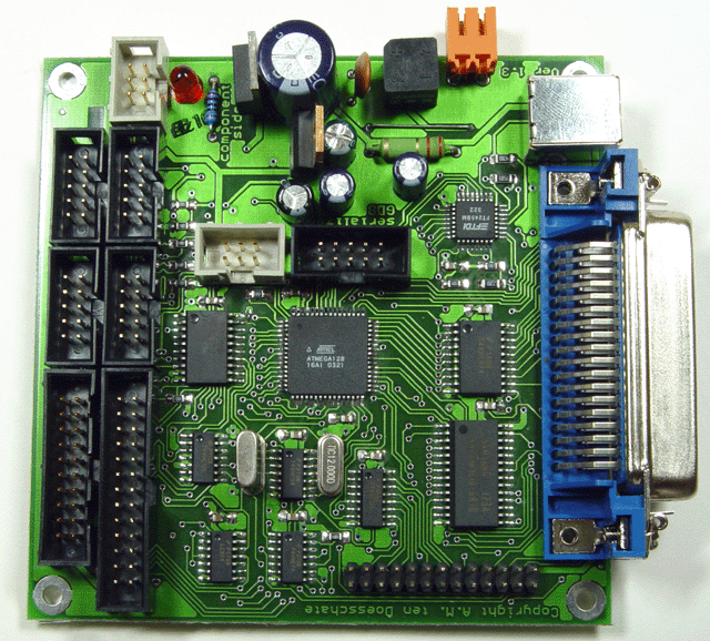
Something different is currently under development, based on Armand ten
Doesschate's
Free AVR ICE / GDB-Serializer. This board will be connected to the
PC's
parallel port or the USB port. Not much had been done to the software so far.
It is
planned to support JTAG debugging of many different devices and to work with
the
GNU Debugger. The photo below shows one of the first four prototypes.