Assembly Instructions
|
EIR boards are shipped with all SMD parts populated, but THT parts packed seperately for DIY soldering. »A video shows the soldering of the through-hole parts. |

|
|
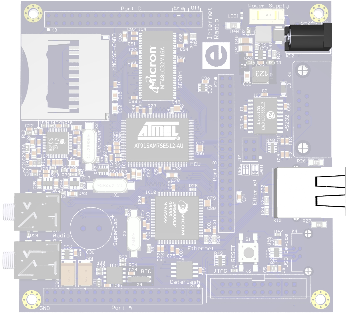
Start soldering
1. Ethernet connector K10 Because the firmware had been preloaded on the SMD board, you should be able to receive and listen to Internet radio stations with this minimal setup. |
|
|
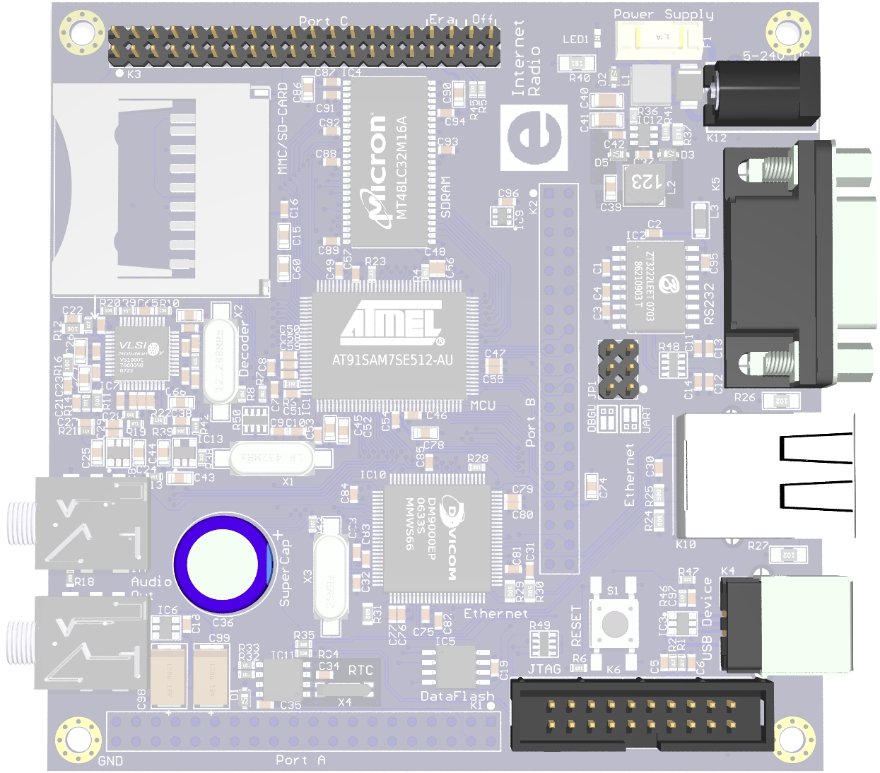
In order to be able to erase and the Flash memory and upload new firmware, we need to mount
3. Expansion port connector K3 (or at least pins 34 and 36) |

|
|
If things are not working as expected, it would be a good idea to make use of
the serial port,
where the following parts are needed.
5. RS-232 jumper block JP1 |

|
|
In order to use the JTAG interface, mount the 7. JTAG connector K6 |

|
|
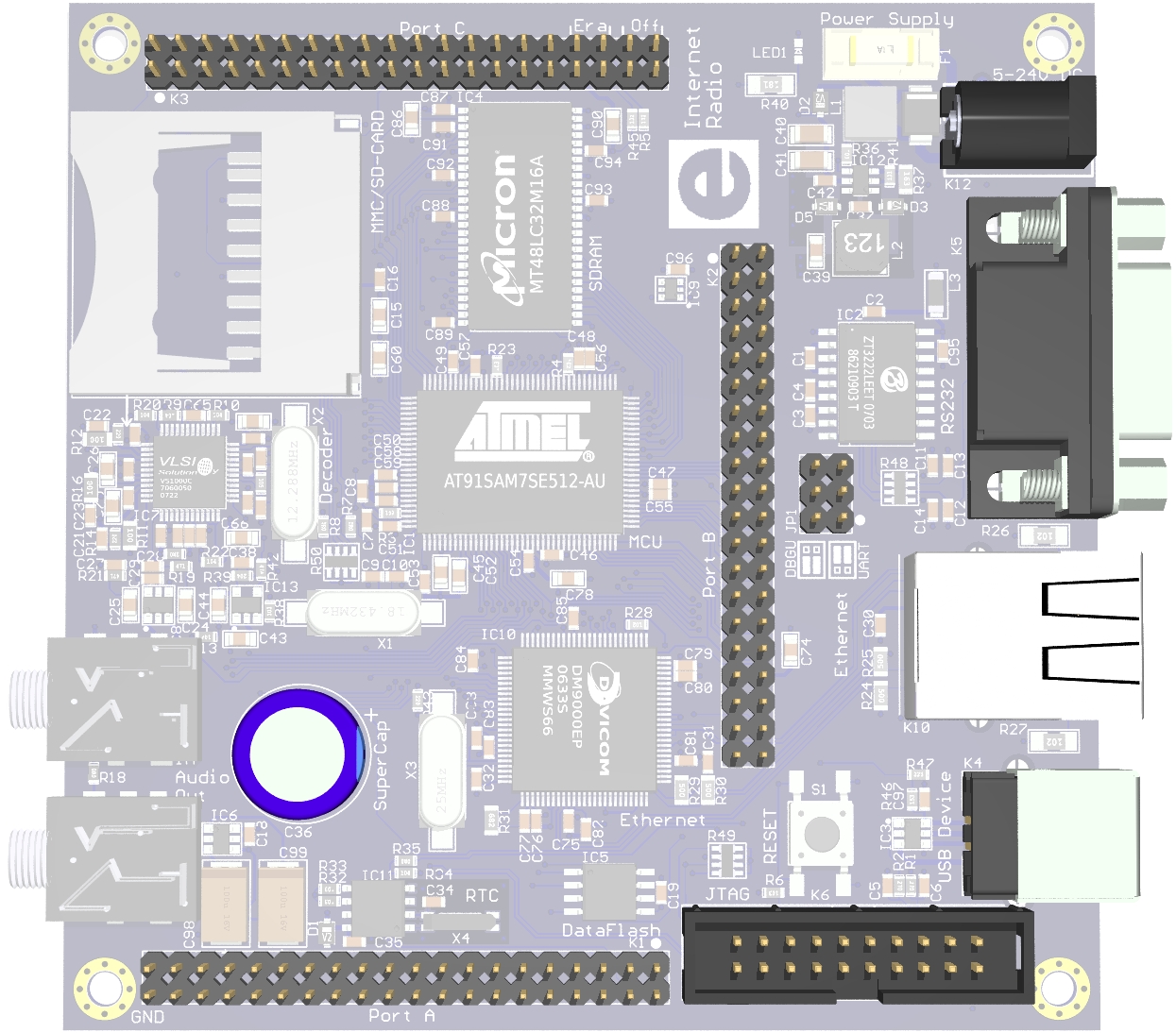
For RTC backup during power loss, mount the 8. Double layer capacitor C36 |
|
|
Finally, if you intend to attach an add-on board, K3 should have been fully
populated. Additionally mount 9. Expansion port connectors K1 and K2 |
|
|
Finished! |

|