 *
 * $Log$
 *
 *
Definition in file tlv320dac.c.
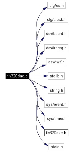
#include <cfg/os.h>
#include <cfg/clock.h>
#include <dev/board.h>
#include <dev/irqreg.h>
#include <dev/twif.h>
#include <stdlib.h>
#include <string.h>
#include <sys/event.h>
#include <sys/timer.h>
#include "tlv320dac.h"
#include <stdio.h>
Include dependency graph for tlv320dac.c:
Go to the source code of this file.
Data Structures | |
| struct | _PCM_BUFFER |
| PCM buffer type. More... | |
Defines | |
| #define | TWI_SLA_DAC 0x1A |
| #define | TLV320DAC_VOL 0x18 |
| #define | SAMPLE_BUFFERS 32 |
| #define | DACI2S_PIO_ID PIOB_ID |
| #define | DACI2S_PINS_A _BV(PB18_TD0_A) | _BV(PB17_TF0_A) | _BV(PB16_TK0_A) |
| #define | DACI2S_PINS_B 0 |
| #define | DACI2S_PDR PIOA_PDR |
| #define | DACI2S_ASR PIOA_ASR |
| #define | DACI2S_BSR PIOA_BSR |
| #define | PCM_CHANS 2 |
| Number of channels. | |
| #define | PCM_BITS 16 |
| Number of bits per sample. | |
Typedefs | |
| typedef _PCM_BUFFER | PCM_BUFFER |
| PCM buffer type. | |
Functions | |
| static void | I2sPdcFill (void) |
| Set PDC pointer and counter registers. | |
| static void | I2sInterrupt (void *arg) |
| SSC interrupt handler. | |
| u_char | Tlv320DacReadReg (u_int reg) |
| Read value from specified DAC register. | |
| void | Tlv320DacWriteReg (u_int reg, u_int val) |
| Write value to specified DAC register. | |
| static int | Tlv320I2sEnable (u_int rate) |
| Enable I2S interface with a given rate. | |
| static int | Tlv320I2sDisable (void) |
| Disable I2S interface. | |
| static int | Tlv320I2sInit (u_int rate) |
| Configure the SSC for I2S mode. | |
| int | Tlv320DacSetRate (u_int rate) |
| Register address. Sampling rate LSB. USB clock mode. Register address. Sampling rate LSB. Base oversampling rate. USB clock mode. Register address. Sampling rate LSB. Base oversampling rate. USB clock mode. Register address. Sampling rate LSB. USB clock mode. Register address. Sampling rate LSB. Base oversampling rate. USB clock mode. Register address. Sampling rate LSB. USB clock mode. | |
| int | Tlv320DacInit (u_int rate) |
| Initialize TLV320AIC23B DAC interface.Register address.Register address. Line input off. Register address. Register address.Register address. DAC select. ADC microphone input. Microphone boost. Register address. Register address. Maser mode. I2S format, MSB first, left 1 aligned. Register address. Interface active. Register address. Left/right simultaneous volume/mute update. Volume control LSB. | |
| static int | Tlv320DacStart (void) |
| Start transmitting audio samples. | |
| int | Tlv320DacFlush (void) |
| Wait until all buffered samples have been transmitted. | |
| int | Tlv320DacWrite (void *buf, int len) |
| Add audio samples to the TLV320AIC23B transmit queue. | |
| int | Tlv320DacSetVolume (int left, int right) |
| Set volume.Register address. Register address. | |
Variables | |
| static HANDLE | i2s_que |
| I2S event queue. | |
| static PCM_BUFFER | pcm_bufq [32] |
| static volatile u_int | brd_idx |
| static u_int | bwr_idx |
|
|
Definition at line 60 of file tlv320dac.c. |
|
|
Definition at line 67 of file tlv320dac.c. |
|
|
Definition at line 75 of file tlv320dac.c. |
|
|
Definition at line 92 of file tlv320dac.c. |
|
|
Definition at line 93 of file tlv320dac.c. |
|
|
Definition at line 94 of file tlv320dac.c. |
|
|
Definition at line 104 of file tlv320dac.c. |
|
|
Definition at line 105 of file tlv320dac.c. |
|
|
Definition at line 106 of file tlv320dac.c. |
|
|
Number of channels.
Definition at line 121 of file tlv320dac.c. |
|
|
Number of bits per sample.
Definition at line 126 of file tlv320dac.c. |
|
|
PCM buffer type.
|
|
|
Set PDC pointer and counter registers. SSC interrupts must have been disabled befor calling this function. Definition at line 149 of file tlv320dac.c. 00151 { 00152 if (brd_idx != bwr_idx) { 00153 if (inr(SSC_TNCR) == 0) { 00154 if (++brd_idx >= SAMPLE_BUFFERS) { 00155 brd_idx = 0; 00156 } 00157 outr(SSC_TNPR, (u_int) pcm_bufq[brd_idx].wbf_dat); 00158 outr(SSC_TNCR, pcm_bufq[brd_idx].wbf_len); 00159 } 00160 }
|
|
|
SSC interrupt handler. Called when PDC transmission done. Definition at line 167 of file tlv320dac.c. 00169 { 00170 I2sPdcFill(); 00171 NutEventPostFromIrq(&i2s_que);
|
|
|
Read value from specified DAC register. Not implemented, because the TLV320AIC23B is a write-only device.
Definition at line 182 of file tlv320dac.c.
|
|
||||||||||||
|
Write value to specified DAC register. Communicates with the DAC chip via TWI.
Definition at line 195 of file tlv320dac.c. Referenced by Tlv320DacSetRate(). 00197 { 00198 u_char txdata[2]; 00199 00200 txdata[0] = (u_char)(reg << 1) | (u_char)(val >> 8); 00201 txdata[1] = (u_char)val; 00202 TwMasterTransact(TWI_SLA_DAC, txdata, 2, NULL, 0, 0);
|
|
|
Enable I2S interface with a given rate.
Definition at line 211 of file tlv320dac.c. 00213 { 00214 /* Enable SSC clock. */ 00215 outr(PMC_PCER, _BV(SSC_ID)); 00216 00217 /* Select SSC peripheral functions. */ 00218 outr(DACI2S_ASR, DACI2S_PINS_A); 00219 outr(DACI2S_BSR, DACI2S_PINS_B); 00220 00221 /* Enable SSC peripheral pins. */ 00222 outr(DACI2S_PDR, DACI2S_PINS_A | DACI2S_PINS_B); 00223 00224 /* Configure 16-bit stereo I2S transmit format. */ 00225 outr(SSC_CMR, 0); 00226 outr(SSC_TCMR, /* Set transmit clock mode. */ 00227 SSC_CKS_TK | /* Use external clock at TK. */ 00228 SSC_START_EDGE_RF | /* Start transmission on any edge. */ 00229 (1 << SSC_STTDLY_LSB)); /* Delay start by 1 cycle. */ 00230 outr(SSC_TFMR, /* Set transmit frame mode. */ 00231 ((PCM_BITS - 1) << SSC_DATLEN_LSB) | /* Transmit 16 bits. */ 00232 SSC_MSBF); /* Most significant bit first. */ 00233 00234 /* Enable transmitter in PDC mode. */ 00235 outr(SSC_PTCR, PDC_TXTEN); 00236 outr(SSC_CR, SSC_TXEN); 00237 00238 return 0;
|
|
|
Disable I2S interface.
Definition at line 245 of file tlv320dac.c. 00247 { 00248 /* Disable all interrupts. */ 00249 outr(SSC_IDR, 0xFFFFFFFF); 00250 00251 /* Disable SSC interrupt. */ 00252 NutIrqDisable(&sig_SSC); 00253 00254 /* Disable SSC clock. */ 00255 outr(PMC_PCDR, _BV(SSC_ID)); 00256 00257 /* Reset receiver and transmitter. */ 00258 outr(SSC_CR, SSC_SWRST | SSC_RXDIS | SSC_TXDIS); 00259 outr(SSC_RCMR, 0); 00260 outr(SSC_RFMR, 0); 00261 outr(SSC_PTCR, PDC_RXTDIS); 00262 outr(SSC_PTCR, PDC_TXTDIS); 00263 outr(SSC_TNCR, 0); 00264 outr(SSC_TCR, 0); 00265 00266 return 0;
|
|
|
Configure the SSC for I2S mode.
Definition at line 275 of file tlv320dac.c. 00277 { 00278 /* Register SSC interrupt handler. */ 00279 NutRegisterIrqHandler(&sig_SSC, I2sInterrupt, 0); 00280 00281 Tlv320I2sDisable(); 00282 Tlv320I2sEnable(rate); 00283 00284 /* Enable SSC interrupt. */ 00285 NutIrqEnable(&sig_SSC); 00286 00287 return 0;
|
|
|
Register address. Sampling rate LSB. USB clock mode. Register address. Sampling rate LSB. Base oversampling rate. USB clock mode. Register address. Sampling rate LSB. Base oversampling rate. USB clock mode. Register address. Sampling rate LSB. USB clock mode. Register address. Sampling rate LSB. Base oversampling rate. USB clock mode. Register address. Sampling rate LSB. USB clock mode. < < USB mode : 0=250 fs, 1=272 fs Normal mode: 0=256 fs, 1=384 fs < USB mode : 0=250 fs, 1=272 fs Normal mode: 0=256 fs, 1=384 fs < USB mode : 0=250 fs, 1=272 fs Normal mode: 0=256 fs, 1=384 fs Definition at line 289 of file tlv320dac.c. References DAC_SRATE, DAC_SRATE_BOSR, DAC_SRATE_SR_LSB, DAC_SRATE_USB, and Tlv320DacWriteReg(). 00291 { 00292 switch(rate) { 00293 case 8000: 00294 #ifdef AT91SAM7X_EK 00295 Tlv320DacWriteReg(DAC_SRATE, (3 << DAC_SRATE_SR_LSB)); 00296 #else 00297 Tlv320DacWriteReg(DAC_SRATE, (3 << DAC_SRATE_SR_LSB) | DAC_SRATE_USB); 00298 #endif 00299 break; 00300 case 8021: 00301 Tlv320DacWriteReg(DAC_SRATE, (11 << DAC_SRATE_SR_LSB) | DAC_SRATE_BOSR | DAC_SRATE_USB); 00302 break; 00303 case 44100: 00304 Tlv320DacWriteReg(DAC_SRATE, (8 << DAC_SRATE_SR_LSB) | DAC_SRATE_BOSR | DAC_SRATE_USB); 00305 break; 00306 case 48000: 00307 Tlv320DacWriteReg(DAC_SRATE, (0 << DAC_SRATE_SR_LSB) | DAC_SRATE_USB); 00308 break; 00309 case 88200: 00310 Tlv320DacWriteReg(DAC_SRATE, (15 << DAC_SRATE_SR_LSB) | DAC_SRATE_BOSR | DAC_SRATE_USB); 00311 break; 00312 case 96000: 00313 Tlv320DacWriteReg(DAC_SRATE, (7 << DAC_SRATE_SR_LSB) | DAC_SRATE_USB); 00314 break; 00315 default: 00316 return -1; 00317 } 00318 return 0; 00319 } 00320 00328 int Tlv320DacInit(u_int rate) 00329 { 00330 /* Initialize TWI. */
Here is the call graph for this function:  |
|
|
Initialize TLV320AIC23B DAC interface.Register address.Register address. Line input off. Register address. Register address.Register address. DAC select. ADC microphone input. Microphone boost. Register address. Register address. Maser mode. I2S format, MSB first, left 1 aligned. Register address. Interface active. Register address. Left/right simultaneous volume/mute update. Volume control LSB.
Writing zero to this register triggers reset. < Writing zero to this register triggers reset. Definition at line 339 of file tlv320dac.c. 00360 { 00361 NutIrqDisable(&sig_SSC); 00362 I2sPdcFill(); 00363 outr(SSC_IER, SSC_ENDTX); 00364 outr(SSC_CR, SSC_TXEN); 00365 NutIrqEnable(&sig_SSC); 00366 00367 return 0; 00368 } 00369
|
|
|
Start transmitting audio samples.
Definition at line 376 of file tlv320dac.c. References brd_idx, bwr_idx, and i2s_que. 00376 { 00377 int rc = 0; 00378 00379 while (bwr_idx != brd_idx) { 00380 Tlv320DacStart(); 00381 if ((rc = NutEventWait(&i2s_que, 500)) != 0) { 00382 break; 00383 } 00384 } 00385 return rc;
|
|
|
Wait until all buffered samples have been transmitted.
Definition at line 392 of file tlv320dac.c. 00397 { 00398 u_int idx; 00399 00400 /* Move to the next buffer to write to. */ 00401 idx = bwr_idx + 1; 00402 if (idx >= SAMPLE_BUFFERS) { 00403 idx = 0;
|
|
||||||||||||
|
Add audio samples to the TLV320AIC23B transmit queue.
Definition at line 413 of file tlv320dac.c. References _PCM_BUFFER::wbf_dat, and _PCM_BUFFER::wbf_siz. 00417 { 00418 if (pcm_bufq[idx].wbf_siz) { 00419 free(pcm_bufq[idx].wbf_dat); 00420 pcm_bufq[idx].wbf_siz = 0; 00421 } 00422 pcm_bufq[idx].wbf_dat = malloc(len * 2); 00423 if (pcm_bufq[idx].wbf_dat == NULL) { 00424 /* Out of memory. */ 00425 return -1; 00426 } 00427 pcm_bufq[idx].wbf_siz = len; 00428 } 00429 00430 /* 00431 * At this point we got an available buffer with sufficient size. 00432 * Move the data to it, set the number of valid bytes and update 00433 * the write (producer) index. 00434 */ 00435 memcpy(pcm_bufq[idx].wbf_dat, buf, len * 2); 00436 pcm_bufq[idx].wbf_len = len; 00437 bwr_idx = idx; 00438 00439 return 0; 00440 } 00441 00452 int Tlv320DacSetVolume(int left, int right) 00453 { 00454 /* Cut to limits. */ 00455 if (left > DAC_MAX_VOLUME) { 00456 left = DAC_MAX_VOLUME; 00457 }
|
|
||||||||||||
|
Set volume.Register address. Register address. Sets the master playback gain. Range is +6..-73 dB.
Definition at line 469 of file tlv320dac.c. Referenced by CgiControl(). |
|
|
I2S event queue.
Definition at line 116 of file tlv320dac.c. Referenced by Tlv320DacStart(). |
|
|
Definition at line 138 of file tlv320dac.c. |
|
|
Definition at line 140 of file tlv320dac.c. Referenced by Tlv320DacStart(). |
|
|
Definition at line 142 of file tlv320dac.c. Referenced by Tlv320DacStart(). |
 1.4.4
1.4.4