
Contents
- Introduction
Overview, Features and Copyright - Hardware
Schematics and Eagle CAD files - Firmware
How to program the EEPROM - USB Drivers
PC Installation - Links
Additional resources in the Web
Turtelizer 2 Hardware
PCB Version 2.0 Revision C
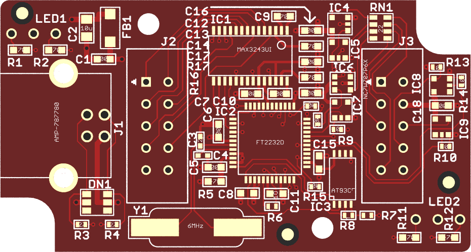
This is the current board revision. Compared to Rev-B, the following changes apply:
While it had been claimed, that Rev-B boards support target voltages down to 1.65V, it turned out, that this was out of specs. In fact, target voltages below 2.5V tend to work unreliable. This has been fixed in Rev-C by replacing two push-pull drivers NC7SZ125P5X (IC6 and IC8) with a single NC7WZ07P6X open collector driver.
An additional signal nTRST had been added to pin 8 of the JTAG connector. In the previous revision this pin was left unconnected.
IC2 FT2232L went out of production and had been replaced by its pin-compatible successor FT2232D. Pins SI/WUA and SI/WUB had been left floating in the previous revision, but are now tied to VCC as recommended in later data sheets.
The input pin FORCEOFF at the RS-232 driver is now connected to the SLEEP output of IC2. This forces the RS-232 driver to power-down after USB suspend. Furthermore, FORCEON of the RS-232 driver is now tied to VCC (permanently enabled) to allow to connect to low power devices.
All series resistors had been changed from 22Ω to 27Ω.
An RC-circuit had been added between digital ground and shield.
- Turtelizer 2.0 Rev-C Schematic
- Turtelizer 2.0 Rev-C CAD files: Can be viewed with the Freeware Version from Cadsoft.
PCB Version 2.0 Revision B
This was the first published revision.
Schematic Page 1:
USB, JTAG and RS232 interface.
Schematic Page 2:
Power Supply.
Board Layout:
Fits in Hammond 1551H.
enclosure.
turtle20b.zip : Eagle CAD
Files. Can be viewed with the Freeware Version from
Cadsoft.
All parts are available in RoHS compliant versions.
USB Interface
For detailed information about the FT2232 USB controller, please visit www.ftdichip.com. An Atmel AT93C56 EEPROM is used to store the configuration data.
A USB type B connector is mounted on the PCB (Tyco 292304 or similar). Power supply for the USB controller and the RS 232 driver is drawn from USB. A transient voltage suppressor array is used to protect the circuit from ESD and a ferrite bead suppresses noise in the power supply line.
JTAG Interface
A 10-pin female header connector is attached to the PCB via a ribbon cable, which is kept short to avoid problems at high transfer rates. The following table shows the connector layout.
| Turtelizer 2 JTAG Connector | |
|---|---|
| TCK - 1 | 2 - GND |
| TDO - 3 | 4 - VTref |
| TMS - 5 | 6 - nSRST |
| Vsupply - 7 | 8 - NC |
| TDI - 9 | 10 - GND |
All JTAG signals are buffered by LCX type single logic gates, which are powered by the JTAG VTref line. This way, the JTAG interface is automatically adjusted to different target voltage levels from 5.5V down to 1.65V. Additional series resistors in the JTAG lines help to maintain signal integrity and even provide some limited overvoltage protection.
RS 232 Interface
A second ribbon cable is used to attach a 9-pin male DSub connector for the RS 232 interface.
| Turtelizer 2 RS 232 Connector | |
|---|---|
| DCD - 1 | |
| 6 - DSR | |
| RD - 2 | |
| 7 - RTS | |
| TD - 3 | |
| 8 - CTS | |
| DTR - 4 | |
| 9 - RI | |
| GND - 5 | |
LED Indicators
Two 3-pin dual color LEDs with common anode are mounted on the back side of the PCB. LED1 indicates JTAG activity. LED2 is lit green when RS 232 data is received and lit red on RS 232 transmits.
JTAG Adapter
Using Turtelizer 2 with standard 14-pin or 20-pin JTAG connectors requires a