
Ethernut 1.3 Hardware
Important Note
Almost all documents including the schematics show or describe the wrong jumper setting for JP2. Furthermore, for some months boards had been shipped with this wrong setting as well.
Both jumpers for the RTS/CTS handshake (JP2, near the RS232 connector) need to connect pins 1 with 2 and 3 with 4. You may alternatively remove these two jumpers.
PCB Version 1.3 Revision H
Changes since Revision G
- LED4 (Ethernet activity) has been inverted to reduce power consumption in RTL8019AS power down mode.
- Board is now protected by a 1A fast acting fuse.
- Rectifier bridge D1, D2, D3 and D4 (S1A) replaced by Schottky barrier rectifier diodes with a forward voltage below 0.5V.
- R9 and C29 added to MR signal to avoid an unintentional board reset in harsh environments.
- 32kHz crystal Y2 replaced by SMD type.
- Capacitors C7 and C8 replaced by SMD types.
- Identification label moved.
- J7 print changed from "ISP" to "SPI".
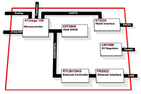
N E W ! A memory map is on this page.
Available I/O ports are listed here.
Known Problems with Version 1.3 Rev.-H
The previously used RS-232 level converter had not been available at the time of production and was replaced by the ZT3222LEET. Unfortunately the RS-232 port shows sporadic data corruption on the receiver side. To fix this, an additional capacitor must be added between pin 16 (GND) and 17 (VCC) of IC6.
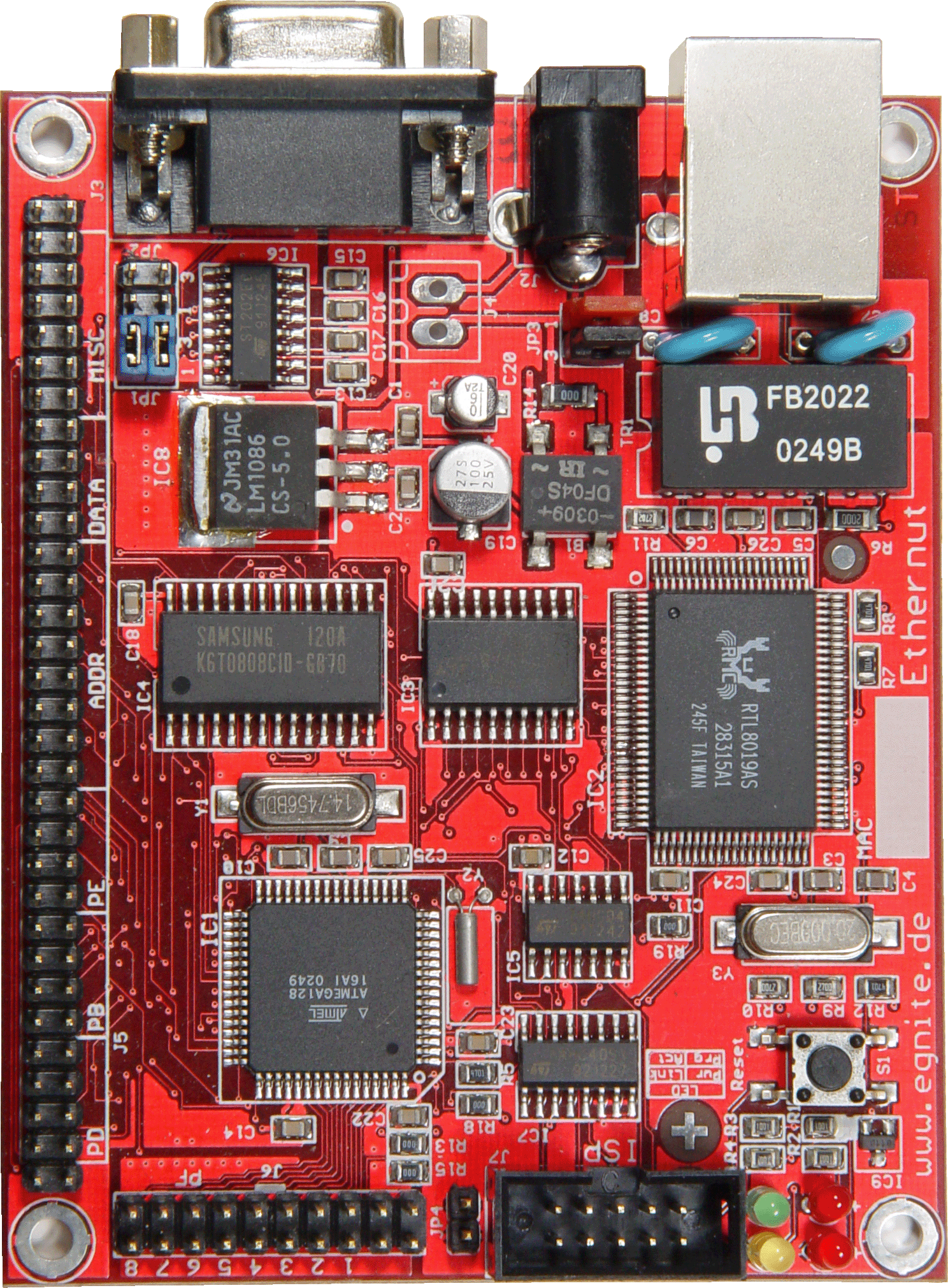
PCB Version 1.3 Revision G
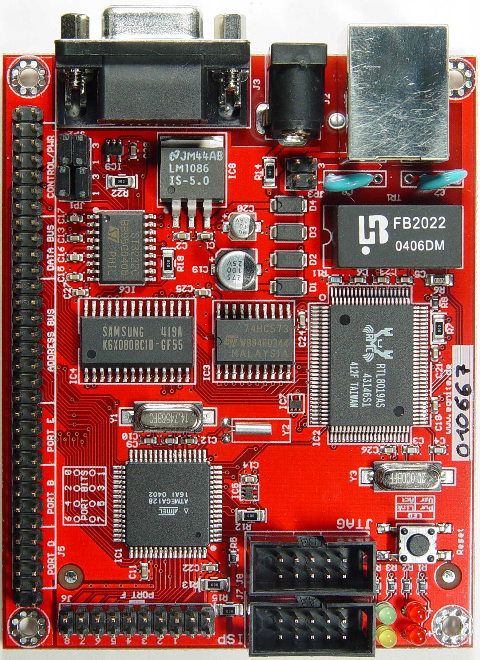
4-layer board with ATmega128 running at 14.7456 MHz, 10 MBit Realtek
Ethernet Controller and 32 kByte external SRAM.
Ethernut 1.3 Rev-G Hardware Manual
(Nov. 2005) Jumper setting corrected.
Changes since Revision F
- Additional JTAG connector added.
- No PROG signal required for SPI programming. Jumper JP4 removed.
- Programming LED has been redefined as User LED connected to PE1.
- ALE signal can be routed to expansion port pin 64 when mounting optional resistor R30.
- EEPROM emulation for RTL8019AS added. Uses A13 and A14 , so no additional port pins are required. This modification allows to clear the full duplex flag in the Ethernet controller.
- Optional resistors allow to use Ethernet interrupts on IRQ5 or IRQ6.
- DS1811 has been replaced by MIC2775, which provides low and high active reset signals. Optional resistors allow to route the reset signal to or from the expansion port.
- Rectifier bridge has been replaced by 4 rectifier diodes.
- Glue logic uses pico gates.
Schematic Part 1: CPU.
Schematic Part 2: SRAM and expansion port.
Schematic Part 3: Ethernet interface.
Schematic Part 4: Power supply and reset logic.
How to Make Rev-G and Rev-H Compatible to Rev-F
Due to the EEPROM emulation, board Rev-G requires Nut/OS 3.9 or later.
However, it is possible to disable EEPROM emulation by removing R7
(0 Ohm 1206 on top of the board near the Realtek)

and mounting R37 (10 kOhm 1206 on the bottom side)
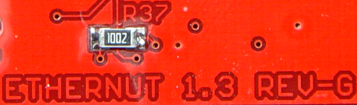
For a more detailed view, klick on the pictures above. Also refer to
part 3 of the schematic.
Known Problems with Version 1.3 Revision G
 The MIC2775 reset controller is very sensitive. A 10k pullup resistor and
a 100n capacitor to ground had been added to the MR/ (manual reset) line.
They are mounted on the back side of the board at the JTAG connector.
Klick on the photo for a larger view.
The MIC2775 reset controller is very sensitive. A 10k pullup resistor and
a 100n capacitor to ground had been added to the MR/ (manual reset) line.
They are mounted on the back side of the board at the JTAG connector.
Klick on the photo for a larger view.
Initial Software
egnite delivers the boards pre-installed with
- basemon.hex
A simple application, which tests all basic board functions and outputs the results on the RS232 line. See the hardware manual for further details. Basemon runs on all Ethernuts and automatically detects the CPU clock and the Ethernet controller. - eboot.hex
The TFTP bootloader for the RTL8019AS Ethernet Controller. More...
Testing Hardware
Updated! testrtl10.zip
This test application for the ATmega128 runs without Nut/OS and does not
require any external RAM. The following steps are performed:
- Scan memory addresses 0x1100 to 0x8300 for an RTL8019AS chip.
- Check if registers are writeable.
- Check for correct jumper mode.
- Verify base address 0x8300.
- Detect and perform EEPROM emulation.
- Scan memory address 0x8300 after EEPROM emulation.
- Stop the controller.
- Reset the controller.
- Test the controller's internal memory (pattern, walking bit, address bus).
- Loopback tests 1, 2 and 3.
- Test for Ethernet link.
- Test controller interrupt request line (PE5 and PE6).
101 RTL8019AS Test 1.0
104 Discovered
100 Write OK
100 Config OK
102 EEPROM emulation OK
101 Re-discovered
101 Stopped
101 Reset OK
100 Memory OK
121 Loopback 1 OK
122 Loopback 2 OK
123 Loopback 3 OK
130 IRQ OK
499 NIC OK
100 Ready for ping 192.168.192.254 (MAC 00:06:98:F0:11:23)
When all tests had been passed, the Ethernut board will be ready to answer ARP and ICMP (ping) requests. The archive contains the full source code, you can adapt the hard coded IP and MAC addresses to your environment.
PCB Version 1.3 Revision F
4-layer board with ATmega128 running at 14.7456 MHz, 10 MBit Realtek
Ethernet Controller and 32 kByte external SRAM.
Ethernut 1.3 Rev-F Hardware Manual (2003)
The original Eagle CAD files are available in the download area.
Schematic Part 1: CPU.
Schematic Part 2: SRAM and expansion port.
Schematic Part 3: Ethernet interface.
Schematic Part 4: Power supply and reset logic.
JTAG How To
Connecting the ATJTAGICE to the Ethernut Board. This requires board Rev D or F.
Known Problems with Version 1.3 Rev.-D
Analog input numbering on the silk screen is mirrored.
SRAM timing may be critical with crystals above 8 MHz. Only one memory failure had been reported so far, but when refering to the datasheets, additional wait states seem to be required. See registers MCUCR in the ATmega 128 datasheet.